68K Addressing Modes
A key concept in computing in both high-
Absolute addressing (the operand specifies the location of the data)
Immediate addressing (the operand provides the operand itself)
Indirect addressing (the operand provides a pointer to the location of the data)
In absolute addressing you specify an operand by providing its location in memory or in a register. For example, ADD P,D1 uses absolute addressing because the location of the operand P is specified as a memory location. Another example of absolute addressing is the instruction CLR 1234 which means set the contents of memory location 1234 to zero.
When you specify a data register as an operand that also is an example of absolute addressing, although some call it register direct addressing.
In immediate addressing the operand is an actual value rather than a reference to a memory location. The 68K assembler indicates immediate addressing by prefixing the operand with the ‘#’ symbol; for example, ADD #4,D0 means add the value 4 to the contents of register D0 and put the result in register D0. Immediate addressing lets you specify a constant, rather than a variable. This addressing mode is called immediate because the constant is part of the instruction and is immediately available to the computer. The addressing mode is also called immediate because the operand is immediately available from the instruction and you don’t have to fetch it from memory or a register. When you specify the absolute address of a source operand, the computer has to get the address from the instruction and then read the data at that location.
Indirect addressing specifies a pointer to the actual operand which is invariably in a register. For example, the instruction, MOVE (A0),D1 , first reads the contents of register A0 to obtain a pointer that gives you the address of the operand. Then it reads the memory location specified by the pointer in A0 to get the actual data. This addressing mode requires three memory accesses; the first is to read the instruction to identify the register containing the pointer, the second is to read the contents of the register to get the pointer. The third is to get the desired operand at the location specified by the pointer.
You can easily see why this addressing mode is called indirect because the address register specifies the operand indirectly by telling you where it is, rather than what it is. Motorola calls this mode address register indirect addressing, because the pointer to the actual operand is in an address register. Consider the effect of executing MOVE (A0),D0
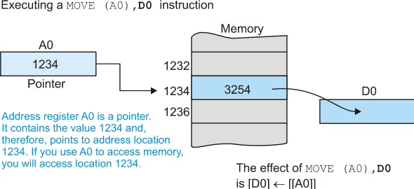
ADDRESS REGISTER INDIRECT ADDRESSING
In the previous diagram, address register A0 points to a memory location. In this case, A0 contains 1234 and points at memory location 1234. When MOVE (A0),D0 is executed, the contents of the memory location pointed at by A0 (i.e., location 1234) are copied into data register D0. In this example, D0 will be loaded with 3254.
Why do we implement this addressing mode? Consider the following two operations
MOVE (A0),D0 ;copy the item pointed at by A0 into D0
ADD #2,A0 ;increment A0 to point to the next item
The first operation loads D0 with the 16-
Address register indirect addressing allows you to step though an array or table of values accessing consecutive elements. Suppose we have a table of 20 consecutive bytes that we have to add together. We can write
MOVE.L #Table,A0 ;A0 points to the table (A0 has the address of Table)
CLR.B D0 ;Use D0 to hold the sum -
MOVE.B #20,D1 ;There are 20 numbers to add
Next ADD.B (A0),D0 ;Add a number to the total in D0
ADD.L #1,A0 ;Point to the next number in the list
SUB.B #1,D1 ;Decrement the counter
BNE Next ;Repeat until all added in
The first three instructions set up the initial values. We load A0 with the address of the numbers. The location has the symbolic name ‘Table’. The # symbol precedes table because A0 is being loaded with the address table and not the contents of that address. Data register D0 holds the sum of the numbers and is cleared prior to its first use. Finally, we put the number 20 into D1 to count the elements as we add them.
The body of the code is in blue. The first instruction fetches the byte pointed at by A0 and adds it to the running total in D0, and the second instruction points to the next byte element in the list. Note that when we increment the pointer we use a longword operation because all pointers are 32 bits.
The last part of the program decrements the element count by one and then branches back to ‘Next’ if we haven’t reached zero. We look at the branching operations in more detail later.
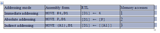
The three addressing modes form a natural progression. The following table defines them in RTL and the figure illustrates these three modes.
Address Register Indirect Addressing with Postincrementing and Predecrementing
An effective computer architecture should be efficient in term of space and speed. Ideally, instructions should exist to convert common sequences of operations into a single instruction; for example, the load effective address instruction LEA (12,A0,D3.L),A2 has the same effect as the three instructions: ADDA.L D3,A0, ADDA #12,A0, and MOVEA.L A3,A2.
We now look at how the power of the 68000's address register indirect addressing mode has been enhanced by letting the 68000 automatically alter the contents of the pointer register each time it is used.
Let's first look at a typical application of address register indirect addressing
in accessing a data structure in which the individual elements are stored consecutively.
For example, consider the following fragment of a program designed to fill a 16-
MOVE.B #16,D0 Set up a counter for 16 elements
LEA BUFFER,A0 A0 points to the first element of the array
LOOP CLR.B (A0) Clear the element pointed at by A0
ADDA.L #1,A0 Move the pointer to point to the next element
SUB.B #1,D0 Decrement the element counter
BNE LOOP Repeat until the count is zero
There’s nothing wrong with this fragment of code and it does what it is supposed
to. However, note that when we use A0 as a pointer (i.e., CLR.B (A0)), we follow
it by the instruction ADDA.L #1,A0 to bump up the pointer. Because this second instruction
frequently follows a memory access employing address register indirect addressing,
the designers of the 68000 have provided two addressing modes to improve its efficiency:
address register indirect with post-
Address register indirect with post-
An exception to this rule occurs when the stack pointer, A7, is used with byte addressing. The contents of A7 are then automatically incremented by 2 rather than one. This restriction is intended to keep the stack pointer always pointing to an address on a word boundary. Some examples should clarify the action of this addressing mode.
Assembly language form RTL definition Action
MOVE.B (A0)+,D3 [D3] ¬ [[A0]] The contents of the memory location whose address [A0] ¬ [A0] + 1 is in A0 are copied into register D3. The contents of A0 are then increased by 1.
MOVE.L (A0)+,D3 [D3] ¬ [[A0]] The contents of the memory location whose address [A0] ¬ [A0] + 4 is in A0 are copied into register D3. The contents of A0 are then increased by 4.
MOVE.W (A7)+,D4 [D40:15] ¬ [[A7]] The 16-
MOVE.B (A7)+,D4 [D40:7] ¬ [[A7]] The 8-
Figure 4.18 illustrates the effect of the 68000's autoincrementing mechanism. The state of the system before and after the execution of a MOVE.B (A0)+,D0 instruction is described. Before the instruction is executed, A0 points at location 1001. After execution, it points at location 1002. The increment is by one because the operand is a byte.
Figure 4.18 The effect of auto-
Consider again the fragment of a program designed to fill a 16-
MOVE.B #16,D0 Set up a counter for 16 elements
LEA BUFFER,A0 A0 points to the first element of the array
LOOP CLR.B (A0)+ Clear an element and move the pointer to the next one
SUB.B #1,D0 Decrement the element counter
BNE LOOP Repeat until the count is zero
Let's look at a second example of this addressing mode. Suppose that a program employs two data tables, each N bytes long, and it is necessary to compare the contents of the tables, element by element, to determine whether they are identical. The following program will do this. The work is done by the CMPM (A0)+,(A1)+ instruction, that compares the contents of the element pointed at by A0 with the contents of the element pointed at by A1, and then increments both pointers. The mnemonic CMPM used in this program stands for compare memory with memory.
TABLE_1 EQU $002000 Location of Table 1
TABLE_2 EQU $003000 Location of Table 2
N EQU $30 48 elements in each table
.
.
.
LEA TABLE_1,A0 A0 points to the top of Table 1
LEA TABLE_2,A1 A1 points to the top of Table 2
MOVE.B #N,D0 D0 is the element counter
NEXT CMPM.B (A0)+,(A1)+ Compare a pair of elements
BNE FAIL IF not the same THEN exit to FAIL
SUB.B #1,D0 ELSE decrement the element counter
BNE NEXT REPEAT until all done
SUCCESS . Deal with success (all matched)
.
.
FAIL . Deal with fail (not all matched)
Address Register Indirect with Pre-
This variant of address register indirect addressing is similar to the one above,
except that the specified address register is decremented before the instruction
is carried out. As before, the decrement is by 4, 2, or 1, depending on whether the
operand is a long word, a word, or a byte, respectively. Figure 4.19 demonstrates
how this addressing mode differs from address register indirect addressing with post-
As you can see from figure 4.19, the address register is decremented before it is used to access an operand in memory. The following two definitions in RTL show how this addressing mode can be applied to word and longword operands.
Assembly language form RTL definition Action
MOVE.W -
[D40:15] ¬ [[A7]] decremented by 2. The contents of the memory location pointed at by A7 are moved into register D4.
MOVE.L -
[D3] ¬ [[A0]] decremented by 4. The contents of the memory location
pointed at by A0 are then moved into register D3.
Figure 4.19 The effect of auto-
Why does the 68000 support both post-
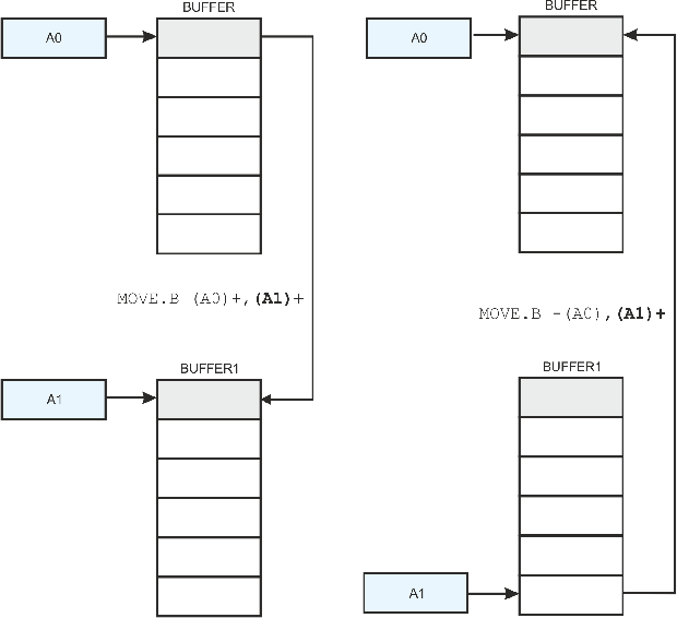
We now demonstrate an example that employs both of these two addressing modes. The order of the 16 bytes in a region of memory called BUFFER is to be reversed. For example, the sequence
12,34,56,78,90,11,22,33,44,55,66,77,88,99,45
is be reversed to give
45,99,88,77,66,55,44,33,22,11,90,78,56,34,12.
There are many ways of reversing the numbers. One method is to swap the top element with the bottom element, and then the next element down from the top with the next element up from the bottom, and so on.
We will employ a very simple but rather crude technique to reverse the order of the
numbers. The contents of BUFFER are copied into a second region of memory, BUFFER1,
using post-
MOVE.B #16,D0 Set up a counter for 16 elements
LEA BUFFER,A0 A0 points to first element of the source array
LEA BUFFER1,A1 A1 points to first element of the destination array
LOOP MOVE.B (A0)+,(A1)+ Move an element from its source to its destination
SUB.B #1,D0 Decrement the element counter
BNE LOOP Repeat until the count = zero and all elements moved
*
* At the end of this operation A0 points to one location beyond
* (i.e., higher than) BUFFER and A1 points to one location beyond BUFFER1
*
MOVE.B #16,D0 Reset the counter for 16 elements
LEA BUFFER1,A0 A1 points to first element of the destination array
LOOP1 MOVE.B -
SUB.B #1,D0 Decrement the element counter
BNE LOOP1 Repeat until the count is zero
Using both post-
Figures missing