The IEEE 488 Bus
Here we look at a rather old but interesting bus -
The IEEE 488 bus dates from 1967 when the Hewlett Packard Company began to look for
a standard bus to link together items of control and test instrumentation. The IEEE
standard was introduced in 1976 and revised in 1978. An updated version of the standard
IEEE 488.2 includes changes to the software environment but no significant modifications
to the underlying physical layer. The IEEE 488 bus is known by several names: the
General Purpose Interface Bus GPIB, the Hewlett Packard Instrument Bus HPIB, IEC
625-
Up to 15 devices can be connected to the IEEE bus to enable them to exchange data at no more than 1 Mbyte/s over a maximum transmission path of 20 m or 2 m per device (whichever value is less). The figure illustrates the relationship between the IEEE bus, the IEEE interface, and the devices that communicate with each other via the bus. As this diagram demonstrates, the IEEE standard covers only the bus and the interfaces but not the devices connected to the interfaces. This distinction is important because we shall soon discover that the IEEE bus implements different communication methods between devices and between interfaces.
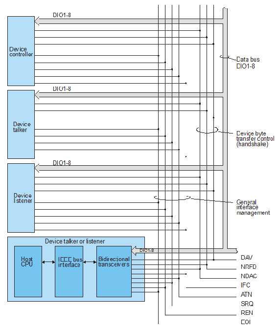
Up to now we have talked about bus masters and bus slaves. The IEEE bus supports three types of device: the controller, the talker, and the listener. A talker or transmitter is a device that can put data on the bus; a listener or receiver is a device that can read data from the bus; and a controller is a device that manages the bus and determines which device may talk and which may listen.
At any instant only one talker can send messages over the IEEE bus, but several listeners may be receiving the messages from the talker. The ability to support a single talker and multiple listeners simultaneously demonstrates a fundamental difference between typical backplane buses and the IEEE bus. Backplane buses transfer data between a master and a single slave, whereas the IEEE bus is able to transfer data between a master (talker) and several slaves (listeners) in one operation, which is, effectively, a broadcast mode of operation. Some modern backplane buses like the Futurebus+ can also operate in a broadcast mode.
Only one controller may be active at any given time, although not every implementation of the IEEE 488 bus requires a controller in, as talkers and listeners can be set up manually. That is, devices can be programmed as permanent talkers or listeners during their manufacture, or by means of switches on their panels. An active controller can give up control of the bus by permitting another controller to take control. In general, the controller is part of the host computer on which the applications program is being run. Furthermore, this computer invariably has the functions of controller, talker, and listener.
The IEEE bus uses 16 information lines that are divided into three distinct groups—the data bus, the data bus control lines and the bus management lines as the figure demonstrates.
Eight data lines, DIO1 to DIO8, transfer data between a talker and one or more listeners,
or between the controller and some or all of the devices connected to the bus. Information
transmitted over the IEEE bus falls into one of three categories: multiline messages
involving the transfer of eight bits of device-
We can categorize the IEEE bus’s three modes of data transmission as follows:
1. A byte of user data or device-
2. A byte of IEEE bus interface control information can be transmitted over the data bus. Control information acts on the interfaces in the devices connected to the bus or affects the operation of the devices in some predetermined fashion defined in the IEEE 488 standard.
3. A single bit of information can be transmitted over one of the five special-
Information flow on DIO1 to DIO8 is managed by three lines control lines, NRFD, DAV, NDAC (i.e., Not Ready For Data, Data Available, and Not Data Accepted). Three control lines are required because all data exchanges between a talker and one or more listeners are fully interlocked, and, if a talker is sending information to several listeners, the data is transmitted at a rate determined by the slowest listener. In general, the operation of the three data bus control lines is controlled by the bus interfaces in the devices connected to the bus, and is entirely transparent to the user. We will describe how these lines function later.
The five bus management lines, IFC, ATN, SRQ, REN, EOI, perform special functions needed to enhance the operation of the bus. In a minimal implementation of the IEEE 488 bus, only one bus management line, ATN, is absolutely necessary. The functions of the bus management lines are summarized as follows.
- ATN (attention) The ATN line distinguishes between two types of message on the eight
data lines. When ATN is true (i.e., electrically low), the information on DIO1 to
DIO8 is interpreted as a control message from the controller. When ATN is false,
(i.e., logical zero or electrically high) the message is a device-
dependent message from a talker to one or more listeners. Note that only the controller can assert the ATN line (or the IFC or REN lines). - IFC (interface clear) The controller uses the IFC line to place the bus in a known state. Asserting IFC resets the IEEE bus interfaces but not the devices connected to them. After an IFC message has been transmitted by a controller for at least 100 ms, any talker and all listeners are disabled, and the serial poll mode (if active) is aborted.
- SRQ (service request) The SRQ line performs the same role as an interrupt request and is used by a device to indicate to the controller that it wants attention. The controller must perform a serial poll to identify the device concerned, using a specified protocol.
- REN (remote enable) The REN line is used by the controller to select between two
alternative sources of device control. When REN is true a device is controlled from
the IEEE bus, and when false it is controlled locally. In general, local control
implies that the device is operated manually from its front panel. The REN line allows
a device to be attached to the IEEE bus, or to be removed from it. In the world of
automated testing, the assertion of REN turns a manually-
controlled instrument into one that is remotely controlled. - EOI (end or identify) The EOI line serves two, mutually exclusive, purposes. Although
the mnemonic for this line is EOI, it is frequently written END (end) or IDY (identify),
depending on the operation being carried out. When asserted by a talker, END indicates
the end of a sequence of device-
dependent messages. That is, when a talker is transmitting a string of device- identify (IDY) function, and causes a parallel poll in which up to eight devices (or groups of devices) may indicate simultaneously whether they require service. The parallel poll is described later.dependent messages on DIO1 to DIO8, the talker asserts EOI concurrently with the last message (i.e., byte) to indicate that it has no more information to transmit. When asserted by the controller in conjunction with the ATN line, the EOI line performs the
The IEEE Data Bus
Data transfers on the IEEE data bus, DIO1 to DIO8, are interesting because they involve
a three-
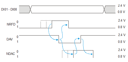
- DAV (Data Valid) When true (i.e., electrically low), DAV indicates to a listener or listeners that data is available on the eight data lines.
- NRFD (Not Ready For Data) When true, NRFD indicates that one or more listeners are not ready to accept data.
- NDAC (Not Data Accepted) When true, NRFD indicates that one or more listeners have not accepted data.
The timing diagram of a data transfer between a talker and several listeners is given
below. Suppose the bus is initially quiet with no transmitter activity and that three
active receivers are busy and have asserted NRFD to inform the transmitter that they
are busy. In this state, the NRFD line will be pulled down by open-
Multiplexing address and data
When one of the listeners becomes free, it releases (i.e., negates) its NRFD output. The negation of NRFD by a listener has no effect on the state of the NRFD line, as other listeners are still holding it down. This situation is shown by dotted lines. When, at last, all listeners have released their NRFD outputs, the NRFD line rises (electrically) to a logical zero state (signifying that the listeners are all not Not Ready For Data—that is, they are ready for data). Now the talker can go ahead with a data transfer.
The talker places data on DIO1 to DIO8 and asserts DAV after a 2 ms data-
Meanwhile, the listeners clamp their NDAC outputs electrically low (i.e., NDAC asserted) to indicate that they have not accepted data. When a receiver detects that DAC has been asserted, it reads the data off DIO1 to DIO8 and negates its NDAC output. That is, if its Not Data Accepted output is false, then it must be signifying data accepted.
Because all listeners must make their NDAC outputs false before the NDAC line can
rise to an electrical high state (i.e., logical zero state), the talker does not
receive a composite data-
Configuring the IEEE Bus
Before the IEEE bus can be used by the devices connected to it, the controller must
first assign one device as a talker and one or more devices as listeners The controller
communicates with all other devices either by uniline messages (asserting one of
the bus management lines), or by multiline messages (asserting ATN and transmitting
a message via DIO1 to DIO8). Multiline messages can be further subdivided into those
intended for all devices (universal commands) and those intended for specific devices
(addressed commands). Remember that all messages use only 7 bits of an 8-
Three multiline messages are used by the controller to configure talkers and listeners
on the bus: MLA (my listen address), MTA (my talk address) and MSA (my secondary
address). Consider first the action of the MLA command. Before a device may listen
to device-
By sending a sequence of MLAs, a group of devices can be configured as active listeners.
The thirty-
Having set up the listeners, the next step is to configure a talker, which is done by transmitting an MTA. There are 31 my talk address codes from 01000000 to 01011110. As only one device can be the active talker at any given time, the act of issuing a new MTA has the effect of automatically disabling the old (if any) talker. The special code 01011111 is called UNT (untalk) and deactivates the current talker. Once a talker and one or more listeners have been configured, data can be transmitted from the talker to the listener(s), at the rate of the slowest device taking part in the exchange, and without the aid (or intervention) of the controller. The format and interpretation of this data is outside the scope of the IEEE 488 standard, but, as we have said, is frequently represented by ISO (ASCII) characters. Note that the controller is acting as an intermediary between talkers and listeners, in contrast to other buses in which potential talkers and listeners are usually autonomous.
Serial and Parallel Polling
Like many other buses, the IEEE 488 bus provides facilities for devices to request service from controllers (i.e., an interrupt mechanism). The IEEE bus supports two forms of supervisor request—the serial poll and the parallel poll, although the parallel poll cannot strictly be classified as an interrupt.
A device connected to the IEEE bus can request attention by asserting the SRQ (service request) bus management line. The controller detects the service request and may respond by initiating a serial poll. A service request, in IEEE bus terminology, corresponds to an interrupt request in conventional computer terminology. As the controller does not know which device initiated the service request, it must poll all devices sequentially. The recommended sequence of actions that should be carried out by the controller in response to a service request is:
Serial-
Unlisten all active listeners with UNL
Enable serial poll with SPE
REPEAT
Transmit a MTA to a device to be polled
Read the response from the polled device
UNTIL all devices polled
Disable serial poll with SPD
Untalk all devices with UNT
End serial_poll
After the controller has entered the serial poll mode, it transmits successive talk addresses, MTAs, and examines the resulting requested service messages from each of the devices addressed to talk, until an affirmative response is obtained. The controller ends the polling sequence by an SPD (serial poll disable) command.
A parallel poll is initiated by the controller and involves several devices concurrently. The controller sets up the parallel poll by assigning individual data bus lines to devices (or groups of devices). For example, device 5 may be told to respond to a parallel poll by asserting DIO3. Then, the controller initiates the parallel poll and the configured devices respond.
The parallel poll is carried out by the controller asserting the ATN and IDY (identify) lines simultaneously. Whenever the IEEE bus is in this state with ATN and IDY asserted, the predetermined devices place their response outputs on the assigned data lines and the controller then reads the contents of the data bus. A parallel poll can be completed in only a few microseconds unlike the serial poll.
The IEEE 488 bus is an old bus that is still going strong because of its widespread
use in the world of computerized instrumentation and test equipment. In many ways,
serial buses such at the Ethernet, USB, FireWire, and even wireless LANs have left
it behind. We have included it because it incorporates several interesting ideas
such as the three-