The RC Circuit
Two components affect the behavior of time-
Engineers began to realize that the simple resistance model of conductors was wrong when very long transmission paths for thousands of kilometers were created.
The first successful transatlantic cable was laid in 1866. However, it was found that using a Morse key (telegraph) to switch current at one end of the cable led to a slowly rising pulse at the other end of the cable. This effect severely limited the rate at which data could be transmitted. William Thomson analyzed the behavior of long cables and developed what later became transmission line theory. The distributed capacitance and inductance of the cable resisted the propagation of a sharp pulse.
The Capacitor
A capacitor is a two-
Figure 1 The capacitor
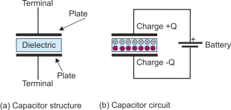
Figure 1(b) illustrates the effect of connecting the capacitor across the terminals
of a battery. The battery creates a potential difference across the places of the
capacitor and that cause a charge to build up on the plates. The electric field across
the dielectric causes the dielectric to become polarized and the molecules to align
as shown in Figure 1(b). The charge on a capacitor is expressed as Q = C.V where
C is the capacitance and V is the voltage across the plates. The capacitance is proportional
to the area of the conductors, the dielectric constant of the insulator and is inversely
proportional to the distance between the places; that is, C = A/t where is the
dielectric constant, A the surface area, and t the distance between the places. The
value of the dielectric constant varies from 1 (a vacuum) to above 7,500 for barium-
The unit of capacitance is the Farad (after Michael Faraday). This is a very large
unit. Audio circuits have capacitors of the order of 100 F (i.e., 10-
Figure 2 shows a simple circuit with a battery, switch, resistor and capacitor. The current through the resistor and capacitor is shown as i(t) because it is a function of time, and the voltage across the capacitor is given as V(t).
Figure 2 The RC circuit
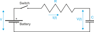
Suppose that, initially, the capacitor is discharged and it has no stored charge with V(t) = 0. When the switch is closed, a current flows equal to V/R because the full battery voltage is across the resistor.
As current flows, a charge builds up on the capacitor and V(t) increases. Since the voltage across the resistor is V – V(t), the current i(t) will drop. At some point the voltage across the capacitor will be V/2 and the current will drop to half its initial value. Ultimately, the voltage across the capacitor will reach V and further current flow will stop.
The charge on a capacitor is Q = C.V. If we differentiate this equation we get dQ/dt = C.dV/dt. Since the value of dQ/dt is (by definition) i(t), we get i(t) = C.dV/dt.
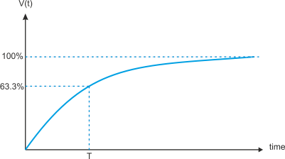
Figure 3 gives the voltage across the capacitor as a function of time. This is an exponential curve and the final voltage is reached asymptotically. In figure 2 the voltage across the capacitor can be expressed as
V(t) = V(1 – e-
The value of RC is called the time constant of the circuit.
Figure 3 Charging the capacitor
When a capacitor is charged, it stores energy. This is one of the prime functions of the capacitor which is used in all ac to dc conversion circuits to hold the output voltage constant while the input voltage is varying. The energy storage of a capacitor is defined as Energy = CV2/2 and is given in Watts. The energy lost in charging capacitors in a digital circuit is significant and is one of the limiting factors in semiconductor design.
All circuits include resistance and capacitance (the capacitance between a wire and its surroundings is often called the stray or parasitic capacitance to indicate its unwanted nature). Consequently, a pulse is always rounded to appear as an exponential rise or fall.