Elementary Introduction to Assembly Language
This article provides a simple introduction to the concepts of computer architecture and assembly language programming. It is intended for those with little or no prior knowledge of these topics and will enable them to read more advanced articles.
To illustrate this article, we use a hypothetical computer called sARM. This is a slightly simplified version of a real computer (i.e., the ARM). I have chosen the ARM as a representative processor because it is a simple but powerful and elegant processor.
I have developed the sARM processor as a teaching tool for this article because it is even simpler than the ARM, and removes some of the practical details that stand in the way of a student’s understanding of assembly language programming. Once you understand, the sARM, converting to the ARM is very easy indeed.
Conventional computers manipulate binary (i.e., two-
Computers use binary arithmetic because we can manufacture two-
Instructions
A computer program carries out a sequence of operations on data. The operations are
called instructions. These instructions are stored in memory and are executed out
one-
0000101010101100101000111001001 may represent a specific computer operation.
Computer instructions may be 8 bits long, 16 bits long, 32 bits long or 64 bits long.
In fact, they may have any length. Generally speaking, we can say that the longer
the instruction the more powerful the computer. Early microprocessors had 8-
Some computers like Intel’s processors so called IA32 family have variable-
The ARM computer has fixed length 32-
The way an instruction is organized (i.e., its bit structure and interpretation) depends only on the computer manufacturer. When we say ‘bit structure’ we mean the way in which the individual bits of an instruction are organized within the word.
An Intel instruction, an ARM instruction, and a Motorola instruction are all totally different and completely incompatible with each other. Intel code runs on Intel chips, and ARM code runs on ARM chips. You cannot run the code intended for machine A on machine B. The term native code is often applied to machine code to indicate that it runs only on one family of computers.
Because very few people can understand machine code, instructions are normally written
in a form of human-
In more formal notation, the assembly language operation ADD r1,r2,r3 can be expressed as [r1] ¬ [r2] + [r2]. This notation is called register transfer language which is abbreviated to RTL. In RTL notation, the symbols [ ] indicate “the contents of”, so that [r1] is read as “the contents of register r1”. Like many other authors, I use courier font to indicate assembly language operations. This is partially because it’s a tradition, and partially because it makes the code more readable by lining up the various fields of an instruction.
Computer Architecture
The term computer architecture describes what a computer does at an abstract level; that is, it tells us what the computer does but not how it does it. A computer architecture tells us what resources a computer has (its registers), what instructions a computer can execute, and how it accesses data in memory (addressing modes). In other words, a computer architecture defines the instruction set of a computer.
Let me repeat a point I made at the beginning. In this article we are going to look
at the ARM’s assembly language for one simple reason. ARM assembly language is
very easy to learn, and far, far easier than, for example, Intel’s IA32 assembly
language. However, to make things even simpler we are going to create a processor
called sARM where the s indicates simple. The sARM’s instruction set is a cut down
version of the ARM’s instruction set. In particular, the sARM computer has an 8-
The differences between sARM and ARM are small – it would not take a student long to convert from sARM to ARM programming. Some of the differences between ARM and sARM are presented at the end of this introduction.
I have also provided a very simple simulator for the sARM that runs in Python (which can be freely downloaded from the Python website for most computers). This will allow students to write and test simple sARM programs.
Registers
All computers have internal locations that hold data called registers. A register is nothing other than a storage element for data inside the computer and is essentially is identical to a memory location.
The only difference between a register and memory location is that a register is part of the CPU and a memory location is part of the memory system. Typically, there are about 8 to 32 registers and 230 memory locations in a computer. The purpose of registers is to hold temporary data during calculations because accessing a register is faster than accessing memory.
The register width (the number of bits that can be stored in a register) is typically
the same as the instruction width – but not always. Fortunately, the register width
and instruction width in the ARM is the same; that is, 32 bits. However, the sARM
that we are using to illustrate a processor has only 8-
Some computers give their registers individual names (often depending on the role
carried out by the register). The sARM has eight general-
All the sARM’s eight registers (r0 to r7) are the same in the sense what you can do to register rx you can do to ry. ; for example, if you can write MOV r3,r7 you can write MOV r3,r7 or MOV r0,r1.
In summary, an ARMs register is a just container that holds eight bits of data. If we write r4 in an instruction we are referring to the 8 bits of data that are stored in register r4.
Instruction Types
We are going to look at the basic instructions implemented by mode computers. These can be categorized into five groups: data movement, arithmetic operations, logical operations, shift operations, compare operations, and branch (or control) operations. Note that some writer combine arithmetic, logical and shift operations and compare operations into one group that they call data processing operations; in other words, they speak of: data movement, data processing, and control operations.
Data Movement
This group of operations moves data from one place to another; that is,
from one register to another register
from a register to memory
from memory to a register.
Note that the term move is misleading. Rather than move, we should say copy because data is copied from place to place. When you move data from A to B, the data in A does not disappear; it is copied to B. The sARM operation MOV r1,r3 copies the data in register r3 to register r1. The data that was in r3 remains unchanged, and the data that was in r1 is overwritten by the new data from r3; consider the following example:
Before MOV r1,r3 After MOV r1,r3
r1 = 00111010 r1 = 00111010
r3 = 11110000 r3 = 00111010
As well as a register, the sARM lets you specify a literal operand (i.e., an actual numeric value). A literal operand is prefixed by the # symbol; for example, to load register r7 with 25 we write MOV r7,#25. If you execute this instruction, register r7 will contain the binary sequence 00011001 which represents the decimal value 25.
How do we know that MOV r1,r2 moves the contents of register r2 to register r1 and not vice versa? Alas, we cannot tell from this instruction. The direction of data movement is a matter of human convention. Some assembly languages move data from left to right and some from right to left. This situation makes moving from one microprocessor to another a bit of a nightmare (a bit like learning a foreign language).
In this introduction to assembly language programming, the direction of data movement is right to left because it’s the convention chosen by those who designed the ARM. However, in order to make it easier remember this convention, I have written the destination operand in bold red font. So, from now on I will write MOV r1,r2 and it will be obvious that r2 is copied to r1 and not vice versa.
By the way, in most computer programs, the data movement group is often the largest group; for example, about 70% of all instructions in a program do nothing other than move data from A to B.
Example
We wish to add 7 and 12. We can write
MOV r0,#7 ;load register r0 with the integer 7
MOV r1,#12 ;load r1 with 12
ADD r0,r0,r1 ;add r0 to r1 and put the sum in r0
Because we can make the second operand in arithmetic and logical instructions a literal, we could have written this cose as:
MOV r0,#7 ;load register r0 with the integer 7
ADD r0,r0,#12 ;add 12 to r0 and put the sum in r0
Number of Operands
A machine-
As well as an operation field, there are zero to, typically, four operands or parameters that describe the instruction. These operands are registers, literals, and other values required to control how the instruction operates. Consider the following:
RTS r0 ;Zero operands (return from subroutine)
NEG r0 ;One operand (negate the contents of r0)
MOV r1,#12 ;Two operands (move 12 to r1)
ADD r0,r1,r2 ;Three operands (add r1 to r2 and store sum in r3)
The operand that specifies where the data goes is called the destination operand. The operand or operands that specify where the data comes from are called source operands.
Arithmetic operations
In everyday arithmetic we use: addition, subtraction, multiplication and division.
Many computers implement the same operations. Consider the sARM operation ADD r1,r2,r3.
This takes the 8 bits in r2 and adds the 8 bits in r3 and then puts the 8-
Before ADD r1,r2,r3 After ADD r1,r2,r3
r1 = 00111010 r1 = 00111010
r2 = 00011011 r2 = 00011011
r3 = 10000001 r3 = 01010101
As you can see, only register r3 changes so that r3 contains 00111010 + 00011011
Examples of the sARM’s subtract, multiply, and divide operations are:
SUB r6,r0,r6
MUL r1,r5,r0 ;multiply [r5] by [r0]
DIV r2,r5,r4 ;divide [r5] by [r4] note that any remainder is lost
The sARM performs all data processing operations on registers. You cannot perform an operation on a memory location other than to load it into a register or to store a register value in memory.
Processors like the sARM that cannot apply a data processing operation to memory are called RISC (reduced instruction set computer). Some processors like the Intel IA32 found in PCs have a CISC architecture and you can perform data operations directly on memory locations.
You can use the same register more than once in a data processing instruction; for example ADD r1,r1,r2 will perform [r1] = [r1] + [r2].
We can even write ADD r4,r4,r4 to get [r4] = [r4] + [r4] = 2 x [r4].
Data processing operations allow you to use a literal as the second source operand; for example, ADD r1,r6,#4 adds 4 to the contents of r6 and deposit the result in r1. Similarly, SUB r0,r0,#1 decrements the contents of r0 by 1.
Example
Suppose we wish to calculate z = (x2 + 4)(y2 + 5) + 10 where y = r1, x = r2, and z = r3. We can write
MUL r2,r2,r2 ;get x2
ADD r2,r2,#4 ;calculate x2 + 4
MUL r1,r1,r1 ;get y2
ADD r1,r1,#5 ;calculate y2 + 5
MUL r1,r1,r2 ;calculate (x2 + 4) * (y2 + 5)
ADD r3,r1,#10 ;calculate (x2 + 4) * (y2 + 5) + 10
Writing this type of program is simply a matter of decomposing an expression into a sequence of simple operations that can be encoded into the appropriate machine language.
Note that the above code reuses registers; for example, register r2 initially contains
the value of x. However, after we execute MUL r2,r2,r2, we have overwritten x in
r2 with x2. If we wish to avoid doing this and we want to preserve the original values
of x and y, we must use other registers as general-
MUL r4,r2,r2 ;get x2 in temporary register r4
ADD r4,r4,#4 ;calculate x2 + 4
MUL r5,r1,r1 ;get y2; in temporary register r5
ADD r5,r5,#5 ;calculate y2 + 5
MUL r4,r4,r5 ;calculate (x2 + 4) x (y2 + 5)
ADD r3,r4,#10 ;calculate (x2 + 4) x (y2 + 5) + 10
Here we’ve used registers r4 and r5 to hold temporary values. We’ve saved x and y in r2 and r1 at the cost of using two additional registers. Actually, you could rewrite the code to preserve r1 and r2 using only one additional temporary register. Can you see how?
Logical Operations
There are three fundamental Boolean operations, AND, OR, and NOT. The sARM can perform an AND or OR operation; for example, AND r2,r3,r4 or OR r6,r7,r6. sARM also includes the common exclusive OR operation, EOR r0,r3,r1.
Logical operations are performed on the corresponding pairs of bits in two words; for example, if we have x = 00110101 and y = 11110011 then
X.Y = 00110101.11110011 = 00110001
X+Y = 00110101+11110011 = 11111011
XÅY = 00110101Å11110011 = 11000110
We can use logical operations to manipulate bits. An AND is used to clear a bit,
an OR to set it, and an exclusive OR to toggle it (i.e., flip it over to its logical
complement). Suppose we have an 8-
AND r0,r0,#111111002 ;clear bits 0 and 1 by ANDing with 0
OR r0,r0,#000011002 ;set bits 2 and 3 by ORing with 1
EOR r0,r0,#001100002 ;toggle bits 4 and 5 by EORing with 1
Shift Operations
A shift operation moves the bits of a register one or more places left or right. For example, shifting 011011101 one place left gives 110111010 and shifting it one place right gives 001101110. Note that when we shift left or right, a new bit enters at one end and a bit drops out at the other end. How we treat the ends of a word being shifted defines the type of shift.
A typical processor implements the following six types of shift. The terms least-
LSL Logical shift left The most-
LSR Logical shift right The least-
ASL Arithmetic shift left The most-
ASR Arithmetic shift right The least-
ROL Logical shift left The most-
ROR Logical shift right The least-
Example
Operation Before After C-
LSL 11001010 10010100 1
LSR 11001010 01100101 0
ASL 11001010 10010100 1
ASR 11001010 11100101 0
ROL 11001010 10010101 1
ROR 11001010 01100101 0
The format of a shift operation is instruction + source register + number of shifts. The number of shifts may be specified as a literal or as the contents of a register; for example we can write:
ASR r1,#1 ;shift the contents of register r1 one place right arithmetically
ASR r1,r3 ;shift the contents of register r1 right arithmetically by the number of places in r3
ROL r2,#4 ;rotate the contents of register r2 four places left
ROR r3,r0 ;rotate the contents of register r3 right by the number of places in r0
The effect of an arithmetic shift left is to multiply an integer by 2, and an arithmetic shift right divides an integer by 2.
Example
We can used shifting to multiply a number by 10 since 10y = 2(4y + y).
MOV r1,r0 ;save a copy of y in r1
ASL r0,#2 ;shift r0 left twice to multiply by 4 to get 4y
ADD r0,r0,r1 ;add y in r1 to get 5y
ASL r0,#1 ;shift r0 left to multiply by 2 to get 10y
Example
Shift operations are often used to extract bits in a word. Consider the 8-
MOV r0,#abcdefgh ;put the data in r0
LSR r0,#4 ;shift r0 right 4 places to get 0000abcd
AND r0,r0,#11110111 ;clear bit 3 to get 0000000bcd
With shifting and logical operations, you can process data in any way you desire.
Compare Operations
In order to implement a high-
The results of a comparison operation set the ARM’s condition code bits (also called
the status flags) in the CCR. Typically, the status flags are Z (zero), N (negative),
C (carry), and V (arithmetic overflow). For example, if we execute CMP r3,r5 and
registers r3 and r5 contain the same value, then the subtraction would yield zero
and the Z-
Note that the Z-
You can either compare two registers or a register and a literal; for example, CPM r3,#12 compares the contents of register r3 with 12.
Consider the following comparisons where we’ve indicated the value of the registers being compared and the effect on the status flags. Remember that CMP r0,r1 computes [r0] – [r1].
r0 r1 C Z N V
CMP r0,r1 5 5 1 1 0 0
CMP r0,r1 5 2 0 0 0 0
CMP r0,r1 2 5 1 0 1 0
CMP r0,r1 200 -
Note that the carry-
A compare operation is not very useful on its own. A comparison is invariably followed by a conditional branch instruction.
Branch Instructions
A branch instruction (sometimes called a jump instruction) changes the sequence in which instructions are executed. This is called a control instruction because it controls the flow of instructions.
There are two types of branch instruction; unconditional and conditional. An unconditional
branch instruction tells the computer to continue executing at a specified point
in the program (it’s the same as a GOTO in certain high-
Fortunately, the programmer does not have to worry about how branch addresses are calculated. The programmer labels the lines he or she wishes to jump to with a label. Consider the following example where we’ve used the label There to indicate the branch target address. The branch instruction has the mnemonic B.
ADD r1,r2,r3 ;do some computing
B There ;go to the line labelled There
There … ;continue executing from here….
The more interesting branch instruction is the conditional branch that forces a branch if and only if a stated condition is true. If the condition is not true, the next instruction in sequence is executed.
Typical conditional branches are
BEQ branch on zero This branch is taken if Z = 1 and is equivalent to branch on equal
BNE branch on not zero This branch is taken if Z = 0 and is equivalent to branch on not equal
BCC branch on carry clear This branch is taken if C = 0 and is equivalent to branch on carry not set
BCS branch on carry set This branch is taken if C = 1 and is equivalent to branch on carry set
BMI branch on minus This branch is taken if N = 1 and is equivalent to branch on negative
BPL branch on carry set This branch is taken if N = 0 and is equivalent to branch on positive
Let’s take an example. Suppose we want to implement the high-
If x = 0 then y = y + 3
We can compare x with 0 and then skip past the “add 3 to y” operation if x is not 0. We will assume that x is in register r1 and y is in r3. That is;
CMP r1,#0 ;compare x (in r1) with 0
BNE NotZero ;skip the addition if result not zero
ADD r3,r3,#3 ;if x was zero we execute this
NotZero . . . ;here’s where we fall out of this code
In this example, the operation CMP r1,#0 subtracts 0 from the contents of register
r1. Only if r0 contains 0 with the Z-
Example
Let’s now add up the first ten integers. We need to implement:
sum = 0
i = 0
Repeat
i = i + 1
sum = sum + i
Until I = 10
We can code this as follows. By the way, it’s up to the programmer to decide how to assign registers to variables.
MOV r0,#0 ;sum (in r0) is 0
MOV r1,#0 ;i (in r1) is 0
Repeat ADD r1,r1,#1 ;i = i + 1
ADD r0,r0,r1 ;sum = sum + i
CMP r0,#10 ;have we reached 10 yet?
BNE Repeat ;continue until all done
;fall through to here
Example
Let’s code an if…then…else statement. We will use
If x = 3 then y = y + 4 else y = y – 5
Assuming x is in r2 and y is in r3, we can write
CMP r2,#3 ;is x = 3?
BNE Not3 ;if not then skip the if part
ADD r3,r3,#4 ;x = 3 so do the if part
B OutIt ;and skip the else part
Not3 SUB r3,r3,#5 ;x not 3 so do the else part
OutIt . . . ;here’s where we exit this construct
The if…then…else construct is not elegant in assembly language because you have to use an unconditional branch to skip past the second condition.
By the way, we could have written the code in an alternate form by swapping the conditions as follows.
CMP r2,#3 ;is x = 3?
BEQ Is3 ;if it is then skip the else part
SUB r3,r3,#5 ;x not 3 so do the else part
B OutIt ;and skip the if part
Is3 ADD r3,r3,#4 ;x = 3 so do the it part
OutIt . . . ;here’s where we exit this construct
Addressing Modes
Addressing modes concern all the ways in which we can express the location of an operand. The sARM’s architecture has only three addressing modes – two of which we’ve already met.
- The contents of a register; for example, ADD r1,r2,r3 specifies three operands, all of them in registers.
- A literal operand. The operand used by an instruction can be a literal (also called an immediate) value; for example ADD r1,r2,#12 specifies the literal operand 12.
- Pointer-
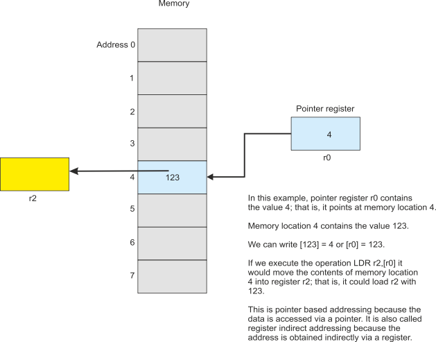
based . In this case a register contains the address in memory of the operand. Only two sARM instructions can use this addressing mode, LDR (load register) and STR (store register).LDR r0,[r1] loads register r0 with the contents of memory whose address is in r1 . Similarly, STR r3,[r2] stores the contents of register r3 in the memory location pointed at by register r2.Pointer-based addressing has several names. Some call it register indirect addressing and some call it indexed addressing. What is important is that the address of the operand is in a register, and that address is a variable because we can change the contents of a register.
Consider the following.
MOV r0,#20 ;load r0 with the value 20
LDR r1,[r0] ;load r1 with the contents of memory location 20
ADD r0,r0,#1 ;increment the pointer register r0 by 1
;in case you missed it … r0 now contains 21
LDR r2,[r0] ;load r2 with the contents of memory location 21
In this example we load two registers r1 and r2 with consecutive locations in memory using the same source address [r0]. We can do this because we’ve changed the value of r0 between the two operations.
The following figure illustrates register indirect addressing.
Pointer-
Example
Suppose we want to add ten numbers that are stored in consecutive locations in memory
starting at location 100. We can use pointer-
MOV r0,#0 ;clear the sum in r0
MOV r1,#10 ;r1 is the loop counter -
MOV r2,#100 ;r2 is the pointer – initially at location 100
Loop LDR r3,[r2] ;get a number
ADD r0,r0,r3 ;add it to the total
ADD r2,r2,#1 ;now point to the next number to be added
SUB r1,r1,#1 ;subtract 1 from loop counter
BNE Loop ;if not zero then goto Loop
The two instructions in blue are the pointer use and pointer manipulator instructions.
In the first case, we use pointer-
Note that we use a countdown loop in this example. We set a counter in r1 to 10. At the end of the loop we decrement it with SUB r1,r1,#1. This instruction decrements r1 and sets the condition code flags accordingly. We can then use BNE to loop back if we have not counted down to zero.
Example
Suppose we have a sequence of 16 numbers at location 100 in memory and we want to write them in sequence to location 200 in memory but in reverse order. How do we do it?
This is another case where we can use pointer-
MOV r0,#100 ;r0 points to the source list
MOV r1,#215 ;r1 points to the end of the destination list
MOV r2,#16 ;r2 is the element pointer
Loop LDR r3,[r0] ;get an element from the source list
STR r3,[r1] ;and store it in the destination list
ADD r0,r0,#1 ;increment the source pointer
SUB r1,r1,#1 ;decrement the destination pointer
SUB r2,r2,#1 ;decrement the loop counter
BNE Loop ;and continue until all done
In this case, we move one pointer down by incrementing it and the other up by decrementing it (this is imagining memory as a table with value 0 at the top).
Register Indirect Addressing with Displacement
This is a minor modification of register indirect addressing. The only difference is that the address of an operand is specified by the contents of a register plus a constant, for example
LDR r1,[r0,#4] ;load r1 with the memory pointed at by [r0]+4
If r0 contains the value 123 then the contents of memory location 127 will be loaded into r0. In other words, you can provide an offset to the pointer and say, “I want the access the data X bytes away from the pointer”.
This addressing mode is useful when dealing with arrays. Suppose array Week starting at memory location 100 contains seven consecutive elements corresponding to the 7 says of the week (Sunday first). Consider:
MOV r0,#100 ;r0 point to array Week
LDR r1,[r0,#2] ;r1 contains Tuesday’s data
LDR r2,[r0,#5] ;r2 contains Friday’s data
As you can see, the pointer points to the beginning of a data structure, and the offset lets us select a particular item within the structure.
The Subroutine
It is often necessary to perform a particular action several times during the execution of a program; for example, evaluating a given expression. You could write out the appropriate code and embed it in the program, once for every time you need to carry out that operation. Alternately, you can convey the code into a subroutine and call that subroutine whenever you need it.
Suppose we want to perform the operation x2 + 2x + 12 several times. On each occasion we are going to have to give the subroutine a parameter (i.e., the value of x) and get back a result (the calculated value of x2 + 2x + 12). The following figure demonstrates calling this subroutine three times. We have used register r0 to carry the parameter to the subroutine and r1 to return it.
The actual subroutine can be written as
Calc MUL r1,r0,r0 ;y = x2
ADD r1,r1,r0 ;y = x2 + x
ADD r1,r1,r0 ;y = x2 + 2x
ADD r1,r1,#12 ;y = x2 + 2x + 12
RTS ;return
The subroutine has a name which is needed to identify it. The subroutine also ends with a special instruction, RTS, that was shall define later.
Note that I added x twice to get 2x. I could have multiplied x by 2 and then added that. Doing it this way avoided either overwriting the original value of x or using an additional temporary register.
In order to invoke or call a subroutine, the sARM has an instruction called BSR or branch to subroutine. In this case we, would write BSC Calc, because the label Calc indicates where the subroutine is in memory.
When a subroutine is called using BSR , the address of the subroutine is placed in the program counter (in this case the address of the instruction at the memory location defined by the label Calc). Execution continues from this point and all the instructions of the subroutine are executed.
However, we have a problem. How is a return made from the end of the subroutine back to the instruction immediately after the BSR Calc? The answer is that it is pushed on the stack as the following text explains.
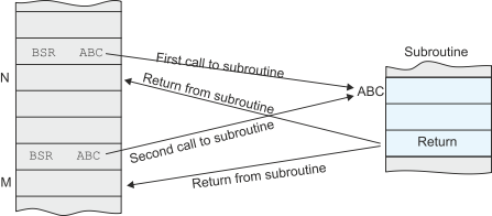
When a BSR is executed, the return address (i.e., the address of the next instruction) is pushed onto the system stack before the jump to the branch target address is made. At the end of the subroutine, the RTS instruction (return form subroutine) pulls the return address off the system stack and execution continues normally.
The following diagram illustrates the concepts of the subroutine call.
Let’s look at a very simple example. We will call the subroutine twice using dummy data. The code is given below and the address of each instruction provided. Note that we set the stack pointer to 100 initially (I chose 100 as the top of the stack – any address would have been possible).
0 MOV SP,#100 ;Top of stack = 100
1 MOV r0,#2 ;x = 2
2 BSR Calc ;call subroutine
3 MOV r1,r4 ;save y
4 MOV r0,#3 ;x = 3
5 BSR Calc ;call subroutine
6 MOV r1,r5 ;save y
7 STOP ;end of program
8 Calc MUL r1,r0,r0 ;y = x2
9 ADD r1,r1,r0 ;y = x2 + x
10 ADD r1,r1,r0 ;y = x2 + 2x
11 ADD r1,r1,#12 ;y = x2 + 2x + 12
12 RTS ;return
Let’s run through this code line by line. Since we use only two registers and the PC and SP, tracing the code is going to be easy. In what follows the values are given at the end of the step.
Step 1 PC = 1 SP = 100 r0 = ?? r1 = ?? instruction = MOV SP,#100
Step 2 PC = 2 SP = 100 r0 = 2 r1 = ?? MOV r0,#2
Step 3 PC = 8 SP = 99 r0 = 2 r1 = ?? BSR Calc
Step 4 PC = 9 SP = 99 r0 = 2 r1 = 4 MUL r1,r0,r0
Step 5 PC =10 SP = 99 r0 = 2 r1 = 6 ADD r1,r1,r0
Step 6 PC =11 SP = 99 r0 = 2 r1 = 8 ADD r1,r1,r0
Step 7 PC =12 SP = 99 r0 = 2 r1 = 20 ADD r1,r1,#12
Step 8 PC = 3 SP = 100 r0 = 2 r1 = 20 RTS
Step 9 PC = 4 SP = 100 r0 = 2 r1 = 20 r4 = 20 MOV r1,r4
Step 10 PC = 5 SP = 100 r0 = 3 r1 = 20 MOV r0,#3
Step 11 PC = 8 SP = 99 r0 = 3 r1 = 20 BSR Calc
Step 12 PC = 9 SP = 99 r0 = 3 r1 = 9 MUL r1,r0,r0
Step 13 PC =10 SP = 99 r0 = 3 r1 = 12 ADD r1,r1,r0
Step 14 PC =11 SP = 99 r0 = 3 r1 = 15 ADD r1,r1,r0
Step 15 PC =13 SP = 99 r0 = 3 r1 = 27 ADD r1,r1,#12
Step 16 PC = 6 SP = 100 r0 = 3 r1 = 27 RTS
Step 17 PC = 7 SP = 100 r0 = 2 r1 = 27 r5 = 27 MOV r1,r5
Step 18 PC = 8 SP = 100 r0 = 3 r1 = 27 STOP
The above trace shows the execution of the code. We have highlighted the execution of the two subroutines. Note that the program counter values are the same for each instance of the subroutine because the same code is being executed. What is different is the value of the program counter after the RTS instruction has been executed. In each case it corresponds to the return point; that is, the instruction immediately after the subroutine call.
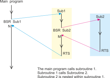
A subroutine can call another subroutine as the following diagram shows.
The Link Register Mechanism
Not all computers have an explicit automatic subroutine call mechanism like the sARM. Some computers (e.g., MIPS, SPARC, ARM) that fall into the RISC category use a link register mechanism to handle subroutine calls and returns.
The ARM provides a link register mechanism as an alternative to the SUB/RTS mechanism. You call a subroutine at location target by executing BL address (the mnemonic BL means branch with link). This action loads the program counter with the address of the subroutine and puts the return address in the link register, lr. This is similar to the BSR except that the return address is stored in a specific register rather than on the stack.
When a return from subroutine is made, the programmer executes MOV PC,lr to copy the return address into the program counter.
What’s the advantage of the link register mechanism over the use of a stack to store the return address? The answer is that it is faster because the return address does not have to be stored in memory.
What’s the disadvantage of the link register mechanism over the use of a stack? The answer is that you can call only one subroutine at a time. If you call a subroutine from within a subroutine (a nested call) then you will overwrite the first return address in the link register. The only way you can nest subroutine calls using the link register mechanism is to save the link register before it is reused (where do you save it … you save it on the stack).
Example
Let’s create a very simple example of a subroutine call and return using the link register mechanism. We will create a subroutine to count the numbers of 1s in a word and then call it three times.
First the subroutine.
Ones ;Counts 1s in r0, returns result in r1, uses r2
MOV r2,#8 ;8 bits to test
Loop ROR r0,#1 ;rotate r0 one place right
BCC NotOne ;if carry clear bit shifted out was not 1
ADD r1,r1,#1 ;if carry set bump up the counter
NotOne SUBS r2,r2,#1 ;decrement the loop counter
BNE Loop ;and continue until all bits tested
MOV PC,lr ;copy link register to PC to return
This subroutine takes register r0 and counts the number of 1s in it and puts the result in r0. Register r2 is uses as a counter and its contents are destroyed by this subroutine (r2 always returns with 0). Note that by using ROR rather than LSR we ensure that r0 is not changed because with 8 rotates r0 ends up where it started. Note that we use SUBS (SUB with S) to indicate that after performing the subtraction we update the condition code registers.
Now we can use this subroutine. Consider.
MOV r0,r6 ;how many ones in r6?
BL Ones ;call the subroutine
.
.
MOV r0,r4 ;how many ones in r4?
BL Ones ;call the subroutine
.
.
MOV r0,#123 ;how many ones in 123 (in its binary form)
BL Ones ;call the subroutine
.
Questions
1. What is a register?
A register is storage location used to store temporary data
2. How many registers are there?
It depends on the processor. The sARM has eight general purpose registers r0 to r7
and three special-
3. What is the difference between a memory location and a register?
They both hold one word of data. However, a register is inside the CPU and is much faster to access. A register has a name (e.g., r0, r1, r3) and there are usually only a small number of registers. A memory location has an address and there are typically 232 or more memory locations. Registers are used to store data during operations; they are sometimes called scratchpad storage.
4. What is the difference between machine code and assembly language?
Machine code is the strings of 1s and 0s that make up a computer program in memory. Each computer family has its own machine code that is incompatible with all other computer families. Because machine code cannot be understood or remembered by people, assembly language was developed as an aid to programmer productivity.
Essentially, there is a one-
However, there are two important differences. Assembly language (like high-
Moreover, modern assemblers include additional facilities such as macros and conditional assembly. Moreover, assemblers can use library routines and link them into programs.
5. How do I load data into a register from memory?
In the sARM processor you must use a load register instruction that looks something like LDR r0,[r1]. This instruction copies the contents of memory location specified by register r1 into register r0? Register r1 is called a pointer register.
6. What addressing mode does LDR r0,[r1] use to access memory? This addressing mode
has various names (depending on which book you read). Some call this register indirect
addressing, some call it indexed addressing, and some call it pointer-
7. How would I load the contents of memory location 124 into register r4?
You would have to set up a pointer to location 124 and then use an LDR instruction; for example,
MOV r0,#124 ;load register r0 with the memory location to access
LDR r4,[r0] ;load register
8. How do I load data from a register into memory?
You use the inverse of LDR which is STR; for example STR r5,[r7] loads the contents of register r5 into the memory location pointed at by register r7.
9. Suppose I wanted to load 12 successive memory locations starting at 200 with the squares of 1, 2, 3, …, 12 to give me 1,2,4,9, …, 144. How would I do it?
You would use pointer based addressing to access memory locations sequentially as follows:
MOV r0,#200 ;r0 points at location 200
MOV r1,#1 ;r1 is the number counter
Next MOV r2,r1 ;take a copy of r1
MUL r2,r2,r2 ;square it
STR r2,[r0] ;store it in memory
ADD r0,r0,#1 ;point to the next location in memory
ADD r1,r1,#1 ;add 1 to the counter
CMP r1,#13 ;have we finished yet?
BNE Next ;if not then continue
10. In the last example, what does BNE Next mean and how does it work?
The BNE instruction is a conditional branch that means branch to the specified location if the condition not equal is true. In this case, the specified location is the line beginning with the label Next. That label is programmer chosen, and I always choose a meaningful name. In order to understand the condition ‘not equal’ we have to look at the previous line.
The instruction CMP r1,#13 means compare the contents of register r1 with the number
13. The comparison is done by subtraction; that is, [r1] – 13. After the comparison,
the condition code flags are set accordingly. For example, if [r1] is 12 then [r1]
– 13 results in 12 – 13 = -
However, on the next cycle round the loop, register r1 is incremented to 13 and the
comparison CMP r1,#13 results in 13 – 13 = 0. Consequently, the Z-
10. You have an array of 64 numbers stored consecutively in memory starting at location 16. Write a program that counts the number of times the value 25 occurs in the array and store it in register r7.
12. What is a subroutine?
13. What is the advantage of a subroutine?
14. What is the disadvantage of a subroutine (compared with simply writing out the appropriate code every time it is used)?
15. What is the stack?
16. What is a nested subroutine?
17. What is the advantage of assembly language programming over programming in a
high-
In assembly language you have direct access to a processor’s resources – registers, instruction set, and addressing modes. You can therefore write programs very efficiently by exploiting the processor’s resources. No compiler can write a program faster than the fastest assembly language version.
18. What is the disadvantage of an assembly language as a means of programming?
Although you can in theory, write a very fast and efficient assembly language program,
it is very difficult for most human programmers to write non-
19. Why do computer architecture textbooks cover assembly language and why is it still taught?
It is true that most computer users and many programmers will never use an assembly
language. However, all users feel the effects of assembly language because that determines
the performance and behaviour of their computer. For example, the performance (speed)
of operations involving arrays or the accuracy of floating-
Another reason for teaching assembly language programming is that it brings into focus the limitations of the underlying architecture in terms of the available operations, addressing modes, and (most importantly) the limitation on the number of available registers.
Appendix Differences between sARM and ARM
Here I am going to point out some of the small difference between the sARM as described in this article and the ARM processor.
The ARM has 16 registers r0 to r15. Registers r14 and r15 have special functions. Register r14 is the link register that stores a return address after a branch with link instruction. Register r15 is the program counter, PC. This is very unusual. The program counter in most processors is effectively hidden from the programmer and cannot be accessed directly.
The ARM is a 32-
The ARM’s condition codes are not set after an instruction is executed (apart from the CMP instruction). If you wish to update the condition codes you must append an S to the mnemonic; for example, SUBS r0,r1,r2 performs the operation [r0] ¬ [r1] – [r2] and then evaluates the appropriate value of the Z, N, C and V flags.
The ARM has a restriction on its multiplication instruction. You cannot use the same register for source and destination; that is, you cannot write MUL r1,r1,r2. Moreover, you can’t use a literal; that is. MUL r1,r2,#12. These restrictions are due to practical design restraints and instruction encoding limitations.
The ARM lacks a divide instruction. If you wish to divide two values you have to write a subroutine to do it in terms of addition, subtraction, and shifting.
The ARM has pointer-
The ARM does not have a built in stack-
The ARM lets you move multiple registers to and from memory in one operation.
The ARM has conditional execution (a most unusual facility). An instruction is executed
if and only if certain conditions are met; for example, ADDEQ r0,r1,r2 means perform
the addition if and only if the Z-
Links to Articles about the ARM on this Website
Article 1: The advantage of using ARM processors in teaching
Article 2: The difference between addresses and data
The PDF version of this file is available here.
Assembler
An assembler and simulatgor for the sARM is available here.
It’s written in python and requires a python environment.
Note that this is in the process of development.