Live Insertion
This article describes the ability to plug things into circuits while the power is on and requires a knowledge of basic electronics.
Not that long ago, it was considered mandatory to switch electronic equipment off
before inserting or removing a card (i.e., module). Today there is a demand for live
insertion systems that permit you to plug a new card into a bus without first powering
down the computer. This facility is also called hot-
In order to support live insertion, the device being inserted must not affect the
operation of the bus during the few milliseconds that insertion takes place. For
example, the FutureBus+ (an early general-
When live insertion occurs, each pin on the inserted device that is connected to
a bus line in the host system must be in a high-
The following discussion is taken from an Philips Semiconductor Application note
by Yong-
Figure 1 provides an electrical model of hot insertion. Figure 1a shows how we can regard the system into which we are inserting the card (i.e., the backplane bus) as a transmission line, and the card itself is can be modeled as a lumped capacitance¾this is largely true if the connector in the card is short and it is driven by typical semiconductor devices.
FIGURE 1 An electrical model of live insertion
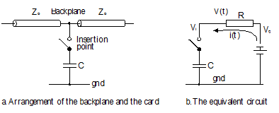
Figure 1b shows the equivalent circuit of the system when the card is inserted. A
time-
Vpeak = Vbus -
where Vbus is the voltage on the bus at the moment of insertion, Vi is the voltage at pin on the card making contact, R is the impedance of the bus (assumed to be resistive), and C is the lumped capacitance of the pin. This equation shows that, at the moment of insertion, the voltage at the pin making contact is initially Vi and rises to Vbus. The exponential rate at which Vi rises to Vbus depends only on the time constant RC. However, since the point of insertion may also represent a mismatch between the impedance of the bus and the pin, the peak voltage at the pin is Vpeak(1 + G), where G is the reflection coefficient at the pin.
If Vswitch is the switching threshold of the bus, the width of the glitch at Vswitch is given by:
tglitch = -
Clearly, anyone designing a live insertion system will strive to minimize the width
of glitches during insertion. Short glitches require the designer to select bus drivers
and with low I/O capacitances. Furthermore, in order to minimize the effect of the
G term, the output rise and fall times of bus-
Semiconductor manufacturers have designed bus drivers that are well suited to live
insertion; for example, figure 10.27 shows the output stage of a bus driver with
a power-
FIGURE 2 Power-

The output buffer is enabled by a NOR gate. When the output of the NOR gate is high the buffer can actively drive the bus. When the output of the NOR gate is low, the output buffer is disabled and the bus is not driven¾the situation required during live insertion.
As you can see from figure 2, the NOR gate has two inputs. One is a conventional
enable, OE*, and the other is derived from a circuit containing a transistor T1 and
two diodes, D1 and D2. When transistor T1 conducts, the voltage at its collector
is low and the NOR gate is enabled. However, in order for T1 to conduct, the voltage
at the Vcc pin must be approximately three times the voltages across a forward-
Shin’s paper describes the results of glitch testing in the laboratory. A bus is pulled up to 5 V by a 3 kW resistor and insertions and removals made while observing the voltage level on the bus. The test was considered failed if a glitch cause the voltage level on the bus to drop below VOHmin = 3 V (this is a conservative test because an error would probably not occur at VOHmin).
Shin found that the best configuration was to hold the data input of the bus driver high, and to connect the driver’s OE* pin to Vcc during the insertion. This configuration passed 99.9% of the insertion tests (all extraction tests were passed). If however, both the bus driver’s OE* and data input pins were connected to Vcc during insertion, only 20% of the insertion tests were successful (all extraction tests were passed).
These results demonstrate that card removal seems to be less prone to errors than card insertion, and that the device characteristics of the bus drivers are very important.