|
Register |
Application |
MIPS Name |
ARM equivalent |
|
0 |
Constant 0 |
$0 or $zero |
No ARM equivalent |
|
1 |
Reserved for the assembler |
$at |
|
|
2 - |
Variables |
$v0 - |
|
|
4 - |
arguments |
$a0 - |
|
|
8 - |
temporary values |
$t0 - |
|
|
16 - |
saved |
$s0 - |
|
|
24 - |
temporary values |
$t8 - |
|
|
26 - |
reserved for kernel use |
$k0 - |
|
|
28 |
Global pointer |
$gp |
|
|
29 |
Stack pointer |
$sp |
r13 = sp |
|
30 |
Frame pointer |
$fp |
|
|
31 |
Return address |
$ra |
r14 = link register |
MIPS -
Here we provide an introduction to the MIPS processor, one of the first reduced instruction set computers. Further details of its history can be found on the MIPS History Page.
First – a Warning
Literature on MIPS processors can be confusing for several reasons; especially to those who did not grow up on MIPS processors. First, the MIPS architecture has evolved and there are more instructions than were incorporated into the original design.
Second, there are some MIPS peculiarities in terms of the consistent use of terminology; the most significant being the use of the letter u that has different meanings in different applications. For example, the reasonably named DIVU instruction performs division with unsigned integers, whereas the woefully misnamed addu instruction performs addition without an exceptions if arithmetic overflow occurs.
Third, MIPS tests the definition of the term ISA, instruction set architecture, to the limit. The term ISA is usually defined as the assembly language programmer’s abstract view of the architecture and the ISA include the registers, instructions, and addressing modes. The designers of assemblers and simulators for MIPS have rather gone to town with the use of pseudo instructions (i.e., operations that are not part of the official ISA but which are translated into other instructions or into groups of instructions by the assembler. This feature can be confusing to the novice, because it often appears that MIPS has more instructions than it really does.
MIPS
The MIPS architecture is not significantly dissimilar to that of the ARM. Both processors
are examples of early RISC architectures, although current MIPS and ARM variations
have come a long way from their first-
MIPS has 32 registers, each of which is 32 bits wide – like ARM. However, there is
a MIPS64 64-
At first sight, MIPS assembly level code seems confusing because of its register
naming convention. MIPS registers are called $0 to $31, whereas the ARM’s registers
are r0 to r15. The use of the $ prefix is part of the MIPS assembler and a rather
odd convention. MIPS programmers (like ARM programmers) follow a convention concerning
the use of registers; for example, MIPS registers r4 to r7 (ok, I mean $4 to $7)
are reserved for passing parameters and can be written $a0 to $a3. The MIPS programmer
can write either add $4,$5,$6 or add $a0,$a1,$a2 since these operations are identical.
By convention, MIPS instructions are written in lower-
MIPS register r0, $0, permanently holds the value 0 and cannot be changed. Consequently, and instruction that specifies register 0 is able to use the constant 0 without having to specify a literal. This is a clever innovation because it provides a significant extension to the ISA without the additional cost of encoding overheads. On the other hand, it loses a register. Note that register $0 can be named zero in MIPS assembly language; for example, OR $1,$1,zero. The following table describes the MIPS register set and its naming conventions/applications.
Of these 32 registers, only r0 and r31 (i.e., $0 and $31) are strictly dedicated
(i.e., as part of the hardware and ISA). Registers $2 to $30 can be used as general-
Load and Store operations
As a classic RISC, the only memory access operations that MIPS supports are load
and store. These operate on 8-
sw Store word lw Load word
sh Store half word lh Load half word
Sb Store byte lb Load byte
MIPS does not provide a lot of choice when it comes to addressing modes for load and store operations. None at all, really. The only addressing mode supported by MIPS is address register indirect with offset. This, of course, is the same as ARMs basic register indirect mode, although variations such as incrementing the register are not allowed. Typical MIPS load and store operations are:
MIPS assembly RTL Operation ARM equivalent
lw $r2,4($r3) [r2] ¬ [4 + [r3]] Load $r2 from memory pointed at by r3 + 4 LDR r2,[r3,#4]
sw $6 ,8($r4) [8 + [r4]] ¬ [ r6] Store $r6 in memory pointed at by $r4 + 8 STR r6,[r4,#8]
Notice the differences between MIPS and ARM assembler styles and despair! ARM uses the # symbol to denote a literal, whereas MIPS doesn’t because the literal is understood. One assembler uses round brackets and the other square brackets. One assembler puts the offset within the brackets and the other puts the offset outside the brackets.
MIPS, unlike ARM and many other processors does not provide a simple register-
Pseudo operation Action Actual MIPS code
MOVE $3,$2 copies register $2 to register $3 addu $2,$0,$2
MOVE $2,$0 clears register $2 because $2 = 0 addu $2,$0,$0
Registers can be loaded with a literal. MIPS provides a 16-
li $4,0x1234 load register $4 with the 16-
Here, the mnemonic li (load literal) indicates the nature of the operand, rather than the use of a tag as in the ARM’s MOV r1,#0xAB.
The operation li is, in fact, a pseudo instruction. The MIPS assembler actually translates the instruction Li $4,0x1234 into ori $4,$r0,0x1234. Performing a logical OR between register r0 (containing 0) and a literal, yields the literal which is copied to the destination register.
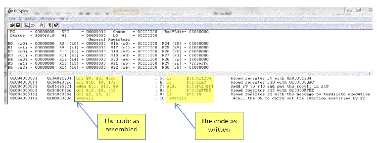
Let’s look at a simple example of MIPS code. We load two registers, add them, load a third register and then stop.
.text #start of program AREA
main: li $t1,0x1234 #load register r9 with 0x00001234 LDR r1,=0x1234
li $t2,0xAC #load register r10 with 0x000000AC MOV r2,#0xAC
addu $t3,$t2,$t1 #add r9 to r10 and put the result in r10 ADD r3,r2,r1
li $t4,0xFFEE #load register r12 with 0x0000FFEE MOV r3,0xFFEE
li $v0,10 #load register r2 with the message to terminate execution MOV r10,N
syscall #call the OS to carry out the function specified by r2 SVC #M
.end main #end of program
At the right of the comment field we’ve provided approximately corresponding ARM instructions in red. Below is a snapshot of the screen when this code has been loaded into the popular, freely available MIPS simulator colled SPIM. By convention MIPS programs are terminated with a call to the operating system that involves loading a constant into a register and then calling a software interrupt (SYSCALL for MIPS which corresponds to SVC for ARM).
The .end main assembler directive terminates the program.
Note some of the differences between MIPS (SPIM) and ARM (Keil) assembly conventions. A SPIM program begins with .text (indented) and the first line must begin with the label main:. SPIM labels are terminated by a colon. ARM comment fields begin with a semicolon and SPIM fields begin with a hash.
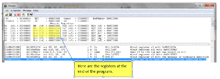
After setting the PC to the start of the code 0x00400000, the code has been executed to give the following result.
Loading 32-
Different RISC processors have different ways of handling 32-
MIPS takes a different approach. Since it can handle a 16-
The use of the load immediate instruction means that you can load a 32-
lui $t0,0x5678 # get the upper-
lui $t0,$t0,0x1234 # concatenate with the low-
MIPS Data-
MIPS has a conventional set of data processing instructions and uses a three operand
register-
add $t2,$t1,$t0 # [t2] ¬ [t1] + [t0] (ARM ADD r2,r1,r0)
addu $t2,$t1,$t0 # [t2] ¬ [t1] + [t0] ignore overflow (ARM ADD r2,r1,r0)
addi $t2,$t1,N # [t2] ¬ [t1] + N (ARM ADD r2,r1,#N
addiu $t2,$t1,N # [t2] ¬ [t1] + N ignore overflow (ARM ADD r2,r1,#N)
sub $t2,$t1,$t0 # [t2] ¬ [t1] -
subu $t2,$t1,$t0 # [t2] ¬ [t1] -
subi $t2,$t1,N # [t2] ¬ [t1] -
subiu $t2,$t1,N # [t2] ¬ [t1] -
mul $t1,$t0 # [hi,lo] ¬ [t1] * [t0] 32-
mulu $t1,$t0 # [hi,lo] ¬ [t1] * [t0] 32-
div $t1,$t0 # [hi,lo] ¬ [t1] / [t0] no ARM equivalent
divu $t1,$t0 # [hi,lo] ¬ [t1] / [t0] no ARM equivalent
and $t2,$t1,$t0 # [t2] ¬ [t1] . [T0] (ARM AND r2,r1,r0)
andi $t2,$t1,$t0 # [t2] ¬ [t1] . N (ARM AND r2,r1,#N)
or $t2,$t1,$t0 # [t2] ¬ [t1] + [t0] (ARM ORR r2,r1,r0)
ori $t2,$t1,$t0 # [t2] ¬ [t1] + N (ARM ORR r2,r1,#N)
nor $t2,$t1,$t0 # [t2] ¬ [t1] + [t0] no ARM equivalent
xor $t2,$t1,$t0 # [t2] ¬ [t1] Å [t0] (ARM EOR r2,r1,r0
xor $t2,$t1,N # [t2] ¬ [t1] Å N (ARM EOR r2,r1,#N)
not $t2,$t1 # [t2] ¬ [t1] (ARM MOVN r2,r1)
Most of these operations are self-
The multiply operation is true 32-
mfhi $t0 # transfer the high-
mflo $t1 # transfer the low-
MIPS Shift Operations
In principal there are 16 types of shift operation (arithmetic, logical, circular, and circular through carry, x2 for left/right x2 for static and dynamic). Most processors don’t provide this full set (although the 68K CISC comes close to it). Indeed, it’s not necessary because you can synthesize one shift from another. MIPS has a very modest number of shift operations:
Instruction Action ARM equivalent
sll $t1,$t2,4 shift left logical 4 places (ARM MOV r1,r2, lsl #4)
srl $t1,$t2,8 shift right logical 8 places (ARM MOV r1,r2, lsr #8)
sra $t1,$t2,1 shift right arithmetically 1 place (ARM MOV r1,r2, asr #1)
srlv $t1,$t2,$t3 shift right logical by the number of place in $t3 (ARM MOV r1,r2, lsr r3)
sllv $t1,$t2,$t3 shift left logical by the number of place in $t3 (ARM MOV r1,r2, lsl r3)
srav $t1,$t2,$t3 shift right arithmetically by the number of place in $t3 (ARM MOV r1,r2, asr r3)
Example of a MIPS Program
Suppose we have to calculate F = (A2 + B + C) x 32 + 4, where A, B, and D are consecutive 32 bits values in memory. We will also assume that the result fits into 32 bits (i.e., we don’t have to consider extended arithmetic). The following code follows typical MIPS assembler conventions. The data area indicated by .data defines and initializes variables and reserves space.
.data # start of data area
A: .word 2 # define 32-
B: .word 3 # offset of B is 4 bytes from A
C: .word 4 # offset of D is 8 bytes from A
D: .space 4 # define 32-
.text # start of program
main: la $t1,A # load register t1 with the address of A
lw $t2,($t1) # load register t2 with the value of A
mult $t2,$t2 # calculate A * A with 64-
mflo $t2 # get low-
lw $t3,4($t1) # get B
add $t2,$t2,$t3 # calculate A*A + B
lw $t3,8($t1) # get C
add $t2,$t2,$t3 # calculate A*A + B + C
sll $t2,$t2,5 # calculate (A*A + B + C) * 32
addi $t2,$t2,4 # calculate (A*A + B + C) * 32 + 4
sw $t2,12($t1) # save result in D
li $v0,10 # load register r2 (v$0) with the terminate message
syscall # call the OS to carry out the function specified by r2
.end main
The following figure demonstrates the effect of loading this code into the MARS MIPS
simulator and executing it. This MIPS simulator conforms to the standards set by
SPIM and reads the same source file (a text file created by Notepad with a .s extension).
The code area is pre-
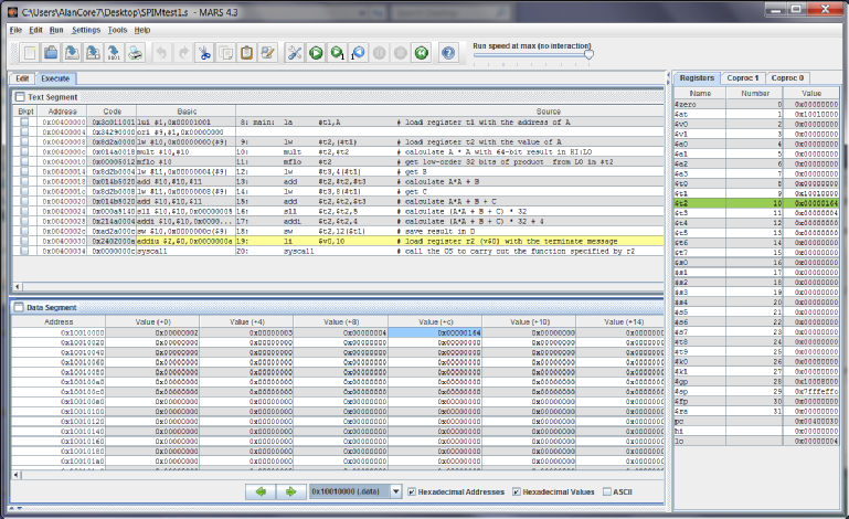
In this example, I’ve declared variable A, set up a pointer in $t1 to A, and then the other variables are accessed by offsets from A; for example variable B is accessed at 4($t1). Although labels B, C, and D are declared in the data area, this is not necessary because these names are not referenced in the rest of the code. However, naming the variables makes it easier to read the program.
Branches and Flow Control
So far, we’ve looked at load and store instructions. The next step is to introduce conditional operations that permit constructs like IF…THEN…ELSE and WHILE X < 4 { action}.
MIPS has an unconditional branch, like ARM and most processors. Its assembly language
form is b target, where target is a label. The target address is stored in the instruction
as a 16-
MIPS conditional branches are unlike those of the ARM, IA32 and 68K architectures. The branch condition is not dependent on a set of flags or condition codes, it is dependent on the outcome of a defined operation. This operation is a register comparison; for example, a branch on zero is written:
beq $t0,$t1,target #branch to target if [t0] = [t1]
All branches use a 16-
The corresponding branch on not equal is:
bne $t0,$t1,target #branch to target is [t0] ¹ [t1]
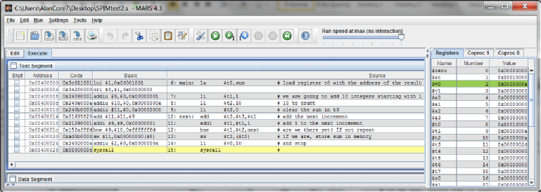
Consider the following example where we use a loop to add the first ten integers and store the result in memory. The code is:
.data # start of data area
sum: .space 4 # define 32-
.text # start of program
main: la $t0,sum # load register t0 with the address of the result
li $t1,1 # we are going to add 10 integers starting with 1
li $t2,10 # 10 to count
li $t3,0 # clear the sum in t3
next: add $t3,$t3,$t1 # add the next increment
addi $t1,$t1,1 # add 1 to the next increment
bne $t1,$t2,next # are we there yet? If not repeat
sw $t3,($t0) # if we are, store sum in memory
li $v0,10 # and stop
syscall #
.end main
The following snapshot demonstrates the assembled code and the register contents after execution.
Other conditional branches are:
blt $t0,$t1,target # branch to target if $t0 < $t1
ble $t0,$t1,target # branch to target if $t0 £ $t1
bgt $t0,$t1,target # branch to target if $t0 > $t1
bge $t0,$t1,target # branch to target if $t0 ³ $t1
There are fewer MIPS conditional branches than is traditional. Other conditions must be synthesized.
MIPS Jumps and Subroutine Calls
MIPS provides three jump instructions. Two of them permit a jump to a semi-
j target # jump to target
jal target # jump to subroutine label and save return address in link register $s31
jalr target # jump to subroutine label and save return address in link register $s31
jr $t0 # jump to address in $t0
The unconditional jump and jump with link are unusual in the sense that they have
a much larger literal than any other MIPS instruction. The literal is 26 bits wide
and is used to generate a 28-
pc31 pc30 pc29 pc28 i25 i24 i23 … i01 i00 0 0
I called this a semi-
The MIPS subroutine call is essentially the same as the ARM equivalent; a jump is executed and the return address is saved in a register. MIPS uses register $31 for this purpose. A return from subroutine is implemented by executing jr $31. Which is normally written jr $a, because the alias of $31 is $a. Consider the following example.
Here we simply use a subroutine to perform the addition. We do not pass the parameters in the registers; that is, the subroutine always adds $t0 to $t1 and returns the result in $t3.
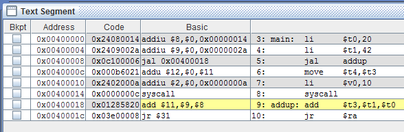
.text # start of program
Main: li $t0,20 # load register $t0 with the value 20
li $t1,42 # load register $t1 with the value 42
jal addup # call a subroutine to do $t0 + $t1 and save the return address
move $t4,$t3 # copy the result to $t4
li $v0,10 # time to go home...
syscall #
addup: add $t3,$t1,$t0 # do the addition leaving the result in $t3
jr $ra # return using the saved address in $ra
.end main
We have indicated the call and return pair in bold red font. The following figure shows the execution of the code immediately after the subroutine has been called by the jal instruction.
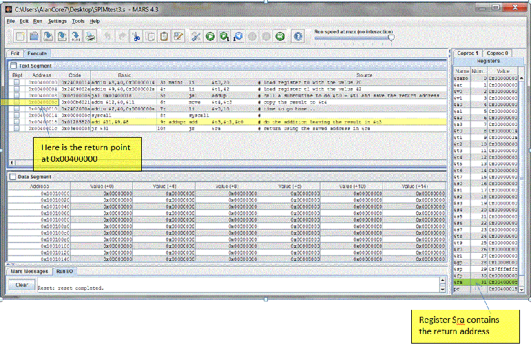
Let’s look at the code in more detail (see the following figure). The jal addup at
memory location 0x00400008 is encoded as 0x0c100006. The least-
Since the pc is currently 0x00400008, the most significant four bits of the pc are 0000. This now gives a branch address of 000000010000000000000000011000 which corresponds to 0x01000018 which is indeed the address of the subroutine.
By convention when a subroutine is called in a MIPS environment, parameters are passed
to the called subroutine in argument registers $a0-
This arrangement is faster than using the stack and is possible because of the MIPS’s relatively large number of registers compared to CISCs and the ARM. Following this convention, we would write the previous code as:
main: li $a0,20 # load parameter register $a0 with the value 20
li $a1,42 # load parameter register $a1 with the value 42
jal addup # call a subroutine to do $a0 + $a1 and save the return address
move $t4,$v0 # copy the result to $t4
li $v0,10 # time to go home...
syscall #
addup: add $v0,$a1,$a0 # do the addition returning the result in $v0
jr $ra # return using the saved address in $ra
.end main
The Set Instructions
MIPS lacks a conventional global condition code register. Branches are made on explicit comparisons; for example bgt $t0,$t1,next forces a branch to the line labelled by next in register $t0 is greater than register $t1. However, you can set up your own flags by using one of the MIPS set instructions. When a set instruction is executed the destination register is set if the comparison is true and cleared otherwise.
The set instructions are:
slt $t0,$t1,$t2 Set on less than signed IF [$t1] < [$t2] THEN [$t0] ¬ 1; ELSE [$t0 ] ¬ 0
slti $t0,$t1,N Set on less than immediate signed IF [$t1] < N THEN [$t0] ¬ 1; ELSE [$t0 ] ¬ 0
sltu $t0,$t1,$t2 Set on less than unsigned IF [$t1] < [$t2] THEN [$t0] ¬ 1; ELSE [$t0 ] ¬ 0
sltiu $t0,$t1,N Set on less than immediate unsigned IF [$t1] < N THEN [$t0] ¬ 1; ELSE [$t0 ] ¬ 0
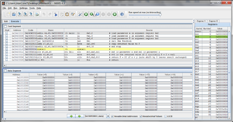
Suppose you require a subroutine that performed if x < y THEN F = 2·Z ELSE F = Z. We can write
slt $t0,$a0,$a1 # $a0 is parameter x and $a1 is parameter y
move $v0,$a2 # $v0 is the returned value of Z (initially F, i.e., $a2)
sllv $v0,$a2,$t0 # return 2·Z if x < y (note shift by 0 leaves result unchanged)
jr $ra # return
Here, we are using the set lower instruction to return the value 0 or 1 in a register,
and then are using that value to perform a zero length shift (no change) or a 1-
Example: Putting things together – Summing the Contents of an Array
Consider the following. We are going to add the 8 wordlength integer elements of an array.
int i, s, a[10];
for (s = i = 0 ; i < 10 ; i++)
s = s + a[i];
main: li $t1,0 # i = 0 MOV r1,#8
li $t2,0 # s = 0 MOV r2,#0
li $t3,8 # Loop limit
la $t4,a # $t4 points to the array a ADR r4,a
loop: lw $t5,0($t4) # Read element of a LDR r5,[r4,#4]
addi $t4,$t4,4 # Increment pointer to next element
add $t2,$t2,$t5 # Add in this element to s ADD r2,r2,r5
addi $t1,$t1,1 # Increment loop transit count I SUBS r1,r1,#1
bne $t1,$t3,loop # Repeat until loop count hits limit BNE loop
I have put the (almost) corresponding ARM code in the comment field. In the ARM version, we count down which enables us to use a simple branch on zero rather than a compare register branch. Moreover, indexed addressing allows us to save an instruction because we don’t need to explicitly update the pointer.
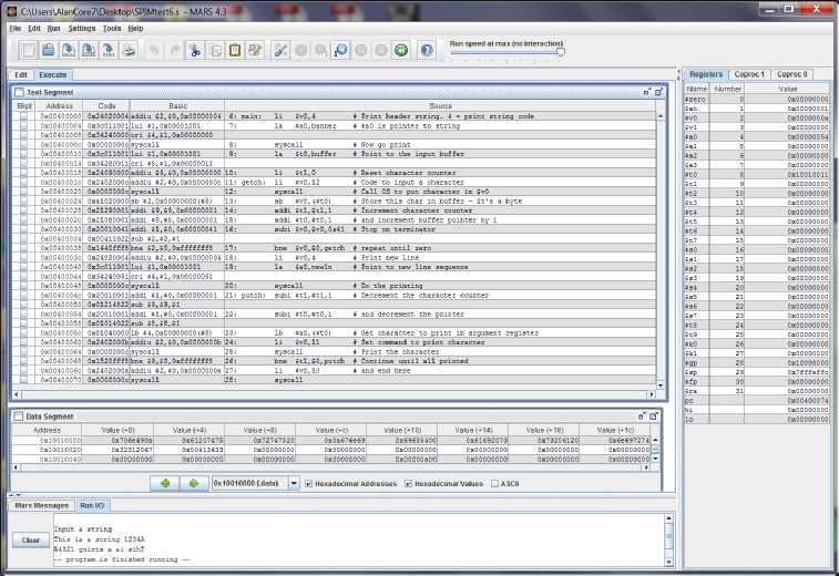
Interlude: The System Call and Further Assembler Directives
All microprocessors have some form of system call or software interrupt or user-
We use the directive .asciiz that creates an ASCII-
.data
banner: .asciiz "\nInput a string\n" # Null terminated ASCII string
buffer: .space 64
newln: .asciiz "\n"
.text
main: li $v0,4 # Print header string. 4 = print string code
la $a0,banner # $a0 is pointer to string
syscall # Now go print
la $t0,buffer # Point to the input buffer
li $t1,0 # Reset character counter
getch: li $v0,12 # Code to input a character
syscall # Call OS to put character in $v0
sb $v0,($t0) # Store this char in buffer -
addi $t1,$t1,1 # Increment character counter
addi $t0,$t0,1 # and increment buffer pointer by 1
subi $v0,$v0,0x41 # Stop on terminator (letter A)
bne $v0,$0,getch # repeat until zero
li $v0,4 # Print new line
la $a0,newln # Point to new line sequence
syscall # Do the printing
putch: subi $t1,$t1,1 # Decrement the character counter
subi $t0,$t0,1 # and decrement the pointer
lb $a0,($t0) # Get character to print in argument register
li $v0,11 # Set command to print character
syscall # Print the character
bne $t1,$0,putch # Continue until all printed
li $v0,10 # and end here
syscall
.end main
In this example, the red font indicate the assembler directives associated with the
text and the blue font indicates the system calls. The .asciiz directive allows us
to enter standard ASCII-
In this example, the codes loaded into parameter register $v0 prior to a system call are:
10 The usual code to terminate a program
4 The code to print a string of characters pointed at by register $a0 prior to the system call
12 The code to input a single character into register $a0
11 The code to print the value in register $a0 as its ASCII equivalent
The code is straightforward. We input a character, increment the character counter, and then store it. We use the sb (store byte instruction) and then increment the character pointer by 1 because we are storing a byte and MIPS is byte addressed.
When we have detected the terminator (in this case an uppercase A) we reverse the process and print a character until the character count winds down to zero.
MIPS to ARM Transition
Some readers will be making a transition from the MIPS world to the ARM world. I have provided a short article on MIPS and ARM differences.