Logic Design Background
This introduction to logic design is intended to provide a background to the BCS syllabus for the Certificate in IT, Computer & Networks Technology paper. The objectives and topics covered by this paper are:
OBJECTIVES:
Use Boolean algebra and other digital design techniques to construct the basic circuits such as adders used to build computers
FUNDAMENTALS
- Number representation (e.g. binary, hexadecimal) and the conversion between bases
- Representation of negative numbers, fractional numbers, and floating point numbers
- Gates: AND, OR, NAND, NOR, EOR, inverter
- Sequential logic elements: D flip-
flops, RS flip- flops, JK flip- flops - Simple logic circuits: Full adder, multiplexer, shift register, counter
- Boolean algebra, simplification of logic equations, truth tables
In this introduction, we do not cover any of these topics; here we put the digital design into a wider context. In particular, we explain why we teach digital design and describe some of the ways in which the subject as practiced today differs from the topics a student traditionally in an elementary introduction.
Digital design is concerned with taking the specification of a system, using a formal notation to describe the system, and then implementing the system using logic devices; for example, you might create a circuit that takes a binary input indicating the month of the year and outputs a circuit that indicates whether the corresponding month has 28, 29, 30, or 31 days. You might need such a circuit in a digital watch.
We begin with a short history of digital design.
Brief History of Digital Design
George Boole (1815 – 1864) was an English mathematician who introduced what we now call Boolean algebra in an article entitled The Mathematical Analysis of Logic in 1847. Boole’s work was destined to provide a basis for the design of modern digital systems. At the time that Boolean algebra was developed, electronics did not exist and no one appreciated how important it would become.
Claude Shannon (1916 – 2001) was one of the greatest engineers and mathematicians of the 20th Century. Shannon took Boole’s algebra and applied it to the design of digital circuits. His classic paper ‘A Symbolic Analysis of Relay and Switching Circuits’ grew out of the master’s thesis that he wrote while at MIT. Shannon also laid the foundations of all today’s communications technology (now called Information Theory).
Although many people associate the development of digital circuits with the EDVAC computer developed at Princeton in the early 1940s by Mauchly and Eckert, some of the earliest digital circuits were created by experimental physicists in the 1930s in order to study cosmic rays and other atomic events. For example, the coincidence detector that determined whether two events were correlated was to form the basis for the AND gate. Bruno Rossi at the University of Florence in Italy is credited with the invention of the AND gate in 1930.
Logic circuits based on electromechanical relays (mechanical switches with moving parts controlled or triggered by electricity) were used in telephone switching networks and the first electromechanical computers (in reality these were calculators rather than computers). Relays gave way to vacuum tubes and vacuum tubes were replaced by transistors in the 1950s. Transistors allowed the construction of relatively small logic elements.
Circuits based on individual or discrete transistors were replaced by integrated circuits in the 1960s and 1970s. An integrated circuit consists of multiple devices (transistors) on a single chip in a single physical package. The concept of the integrated circuit actually dates back to about 1949 when a German engineer, Werner Jacobi, patented the first integrated transistor amplifier (ahead of the then available technology). The first real prototype integrated circuit was patented by Jack Kilby at Texas instruments However, several teams were working on related systems at the same time and credit for the IC is often given to Kurt Lehovec of the Sprague Electric Company who devised a means of electrically isolating circuit elements on a semiconductor crystal. Similarly, Robert Noyce of Fairchild Semiconductor used aluminium metallization to interconnect components in integrated circuits. Because of this almost simultaneous set of developments, it would be unfair to assign the invention of the IC to any single person.
The first integrated circuits were called SSI (small scale integration) and, typically, let you put four gates on a chip. In those days, it took a lot of SSI devices to create a computer. In the early 1960s most integrated circuits were used by the US Minuteman ICBM project. The MSI chip (medium scale integration) followed the SSI and allowed entire functions to be integrated on a single chip; for example, counters, registers, and ALUs.
In the 1970s large scale integrated circuits (LSI) emerged and it soon became possible
to put a primitive microprocessor on a single chip. Intel was the first to create
such a chip with its 4004 4-
In the early 1970s digital design entered a new era when programmable logic devices were introduced. These components provided arrays of simple unconnected gates that could be programmed by the user to implement specific logic configurations. This arrangement allows designer to create custom logic devices using relatively few components. In the late 1970s the FPGA (field programmable gate array) emerged. This device could be easily programmed by the user ‘in the field’ and opened to way to complex digital circuits on a single chip.
Today, complex digital systems are designed by using software packages to specify, design and test circuits. When the software development of the hardware is complete, the design can be loaded into a programmable device and a circuit created.
Digital Design
Here, we put digital design in context by answering a few basic questions about logic design.
- What is logic design?
- Why do students have to learn about it?
- What are the principal practical considerations in logic design?
- Where is logic design going?
What is logic Design?
Electronic circuits are either analog or digital. Analog circuits process time-
Digital circuits represent data in binary form as 1s and 0s and are sometimes called switching circuits because a digital signal can only do two things: remain in its current state or toggle (i.e., switch from a 0 to a 1 or vice versa). Switching circuits were originally devised to control telephone and telegraph switching networks, and then extended to the design of computers.
Since analog signals can be converted into digital form, even systems that were once entirely analog now employ switching technology; for example, the modern television receiver. Similarly, cell phones have analog components to process radio waves, but are largely digital devices.
Logic design is concerned with creating a digital circuit that performs some specified function. For example, a very simple circuit is majority voting circuit where a group of, say, 12 people on a panel each push a button to select ‘yes’ or ‘no’ and the circuit outputs the majority vote. At its most complex, a digital circuit may be a complete computer that uses a billion or more logic devices on a single chip.
Logic design is concerned with taking the specification of a problem and going through all the stages necessary to implement a circuit that will solve the problem. In the example we provide here, a logic system has to be designed that accepts a coded input representing the integers 0,1, 2, 3, …, 14,15 and outputs a single signal that indicates whether the input code represents a prime number or not.
Why do students have to learn logic design?
Logic design is at the heart of all of today’s digital technology. You have to have a background in logic design in order to create a new microprocessor chip. You have to know about logic design if you are going to interface a microprocessor to memory or other devices. You have to know about logic design if you are building a mouse and want to interface its mechanism to a USB interface.
Clearly, those who are destined to build next year’s microprocessors or technicians who have to interface systems to computers have to know about logic design. What about everyone else who is studying computer science and do not intend to be a hardware designer?
Students have to appreciate that logic design is at the heart of all computer technology. The way in which a computer is designed determines its performance (speed) and its capabilities (instruction set). Understanding the basics of logic design makes students aware of the limitations of a computer. Moreover, there are times when understanding the hardware of a computer can even help you to write faster programs.
Although the vast majority of students will never design microprocessors themselves,
many students will interface microprocessors to systems or even have to design special-
What are the principal considerations in logic design?
An elementary course like this teaches students basic Boolean algebra to allow them to take a problem in plain words and to express it as an equation. This is the first step on the way to building a circuit.
Students learn the rules (postulates) of Boolean algebra which allows them to simplify (or otherwise rearrange) equations in order to build the simplest possible circuit.
As well as Boolean algebra students learn about gates that are the physical device (electronic components) that implement Boolean operations. There are only three fundamental types of gate: the AND, OR, and NOT which means that all digital systems can be constructed by interconnecting a large number of these gates. Having created a Boolean expression from a problem in words, you can draw the circuit diagram that represents the arrangement of gates needed to implement the required function.
This is about as far as an elementary first class in digital design gets (i.e., problem,
to Boolean expression, to circuit diagram). In a higher-
Students also have to learn about circuit reliability (how circuits fail) and how to test circuits. It might be very easy to test a trivial circuit that, say, adds together two decimal digits. However, testing the automatic landing system of an aircraft is very much more complicated because many thousands of gates might be involved in the circuit. The following describes in greater detail some of the practical considerations of logic design that students who go beyond an elementary introduction have to consider.
Noise immunity
Noise describes the random signals that are superimposed on logic values. Ideally, if a gate outputs 1.5 V, the signal remains at 1.5 V. In reality there are noise signals that randomly change the output. Noise is generated by many different mechanisms. Thermal noise comes from atomic effects such as the motion of electrons in solids and can never be removed. Noise is also induced by nearby lightning, sparks, and switching transients such as refrigerator and elevator motors starting up. The noise immunity of a gate is a measure of how much noise that can be tolerated before a 1 is recognized as a 0 or vice versa.
Propagation delay
Nothing happens instantaneously. The propagation delay of a gate is a measure of the delay between a change at the input and the corresponding change at the output. If a circuit consists of 10 gates in series and each has a propagation delay of tpd seconds, the total delay of the circuit is 10tpd. Even a piece of wire has a propagation delay because signals cannot travel faster than the speed of light (in many circuits, pulses travel at about 70% of the speed of light in a vacuum).Propagation delay is one of the factors that determine the maximum operating speed of a circuit.
Design for test
If you construct a circuit, you need to test it. Well-
Glitch Free Design
This topic is beyond the scope of the BSC syllabus but it concerns the introduction of spurious transients or glitches in digital circuits. In everyday life you get a glitch when you add, say, 1 to 99. Adding 1 gives 90 with a carry 10, and then adding 10 gives 00 with a carry 100, and adding the 100 gives the final correct result of 100. However, adding 1 to 99 gives 90, 00, 100 in succession where the ‘90’ and ‘00’ are glitches. Now consider a logic circuit. Suppose a signal takes two paths through a circuit from input to output. It is possible that there may be a spurious condition for a very short period before the output becomes final and settles down. Good design techniques can reduce such spurious signals.
Where is logic design going?
Boolean algebra does not change and there are only three fundamental types of gate. Students still design very simple circuits in class today just as they did four decades ago. However, digital design itself has undergone a revolution in the last two decades.
Two factors have changed digital design. The first is the availability of programmable
logic. Up to about 1980 the digital engineer had two choices: build a circuit using
off-
The programmable logic element contains an array of gates on a chip and the connections between gates can be determined by the designer; that is, you can use these logic elements to create your own circuit. Today, engineers can create complex digital circuits without having to write together tens or hundreds of small packages (each containing only a handful of gates).
Originally, programmable logic devices used fusible links (connections that could
be broken by burning out an internal fuse). Today, programmable logic devices work
on similar principles to flash memory and can easily be programmed and reprogrammed.
These devices have become so complicated that you can create circuits as sophisticated
as a computer on a single chip. For example, a camera manufacturer could create a
circuit to implement a focusing algorithm and embed it into a camera’s lens. Indeed,
you could launch a spacecraft to the outer planets with computers composed of programmable
logic elements and then rewire the on-
Not only has the technology required to design digital circuits changed, there has
been a corresponding change in the software tools available. Languages have been
developed to represent circuit specifications. It is now possible to specify a circuit
in a computer-
Programmable logic has entirely revolutionized electronics because you can create
devices as powerful as computers that are directly designed to solve a problem –
unlike a computer that has to run a program. Consequently, you can create very fast
special-
Two hardware description languages, HDLs, are commonly used to design circuits today.
These are Verilog and VHDL. These are rather similar languages – here we will describe
Verilog very briefly. Verilog lets you describe designs in different ways. You can
provide a very high level of abstraction and describe your circuit in an algorithmic
from using code that provides c-
Consider the two-
In Boolean algebra we would write R = P’.X + Q.X
In Verilog we can create a module (which we will call MUX) to perform this action. We can write
module MUX(P,Q,X,R);
input P,Q,X;
output R;
assign R = X ? P : Q;
endmodule
As you can see, this high level description requires very little explanation; it’s
obvious to anyone who has done a little programming. We can also write a lower-
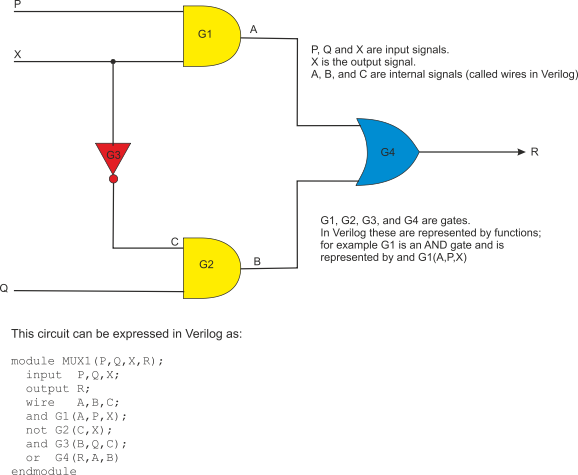
module MUX1(P,Q,X,R);
input P,Q,X;
output R;
wire A,B,C;
and G1(A,P,X);
not G2(C,X);
and G3(B,Q,C);
or G4(R,A,B)
endmodule
This is really a sequence of Boolean operations. In Verilog the reserved word wire is used to indicate intermediate variables (in this case A, B, and C). In this example, we have used three built in functions (gates) and, or, and not. Here G1, G2, G3, and G4 are simply function names and correspond to four gates. The circuit below illustrates this function.
This short excursion into digital design was not intended to teach you how to design complicated digital systems. It is an attempt to show what is out there beyond the ‘event horizon’ of the BCS syllabus and to indicate some of the factors that professional systems designers have to take into account.
Digital Design -
Here we provide an example of a typical problem that students can be expected to solve.
Introduction to Boolean Algebra
Here we provide an elementary introduction to basic Boolean algebra.
Introduction to Gates and Circuits
Here we provide an elementary introduction to basic gates and simple digital circuits.