The PowerPC
The PowerPC is an interesting processor, both because of its architecture and because
of its history or pedigree.
The origins of the PowerPC can be traced back to the IBM 801 project led by John
Cocke in the mid-1970s that evolved into the IBM RS/6000 system. IBM’s architecture
was (and still is) called POWER. The development of this base architecture continued
with the introduction of the model 601 PowerPC by IBM, Motorola, and Apple in 1991.
The goal was to develop a general-purpose personal computer that could be used in
workstations and servers to compete with Intel’s IA32 family.
Motorola had created its own RISC architecture, the 88000 but that family did not
do well in the market place. Motorola hoped that by scrapping the 88000 and jumping
into bed with IBM (remember the saying “No one ever got fired for buying IMB”) and
Apple, success was guaranteed. Initially, it looked as if the PowerPC would be a
success for Motorola and IBM as Apple’s computers adopted PowerPCs.
Motorola’s line of PowerPC processors, G1, G2, G3, G4, G5, never achieved the expected
level of success for several reasons. The WinTel alliance was very strong and potential
adopters were put of using the PowerPC architecture. Motorola has difficulties in
manufacturing the more advanced processors and eventually sold off its semiconductor
arm to Freescale. Apple persisted with PowerPC-based machines for some time and then
joined the IA32 world by using Intel’s processors. Apple dropped the PowerPC because
Apple claimed that it was not keeping pace with development in the IA32 world.
The POWER architecture lives on in the IBM world where the Power 760 is a high-performance
servers and the IBM-Frescale alliance was replaced by an open standards body, Power.org,
in ????. The PowerPC lives on, but largely in embedded applications in automobiles.
It’s RISC Jim, but not as we know it
The PowerPC has a 32-bit RISC architecture. Now, the term RISC is generally taken
to mean reduced instruction set computer. That is, of course, an almost totally wrong
description. Yes, RISC processors like MIPS have rather a lot fewer instructions
than a CISC processor like the 68020. The real difference between RISC and CISC lies
in a regular instruction set size, consistent instruction encoding, and above all
a register-to-register load/store architecture. The PowerPC is a RISC processor in
that sense, not because it has a reduced instruction set. It doesn’t. The PowerPC’s
instruction set is, at first sight, quite bewilderingly complex. Unlike the RISC
I & II, MIPS, and SPARC processors that have comparatively few instructions types
and formats, the PowerPC has fifteen instruction format of which three alone are
used for branching. Some of these instruction formats include fields for extended
opcodes, some include displacement, masking, and immediate fields, and some of the
branch formations include branch addressing using general purpose registers while
others include immediate, absolute, or program counter relative addresses. All of
these features make this a powerful machine at the expense of a more complex compiler
to take advantage of all the features the architecture has to offer.
PowerPC’s Registers
Probably the first question you ask about an ISA is “What registers does it have?”
The PowerPC is a register-to-register RISC with 32 general-purpose registers, like
MIPS. The format of an add instruction is add rD,rA,rB. Note that the PowerPC assembly
language convention is lower-case instruction mnemonics, and the destination operand
on the left. The destination and source registers are generally represented at rA,
rB, and rC in PowerPC literature.
The 32 general-purpose registers r0 to r31 are 32 bits wide (in 32-bit implementations
of the PowerPC and 64 bits wide in 64-bit implementations). Register r0 is not wired
to zero a la MIPS. The following figure shows the structure of a general-purpose
PowerPC register.
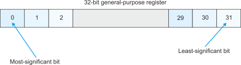
At first sight, this looks like any other register. Look again and you can see that
the least-significant bit is bit 31; in other words, the bits are numbered in reverse
order to those of the ARM, MIPS, and IA32 architectures. If you move from a 32-bit
power PC to a 64-bit power PC, the least-significant bit changes from bits 31 to
bit 63. Although this bit numbering scheme is perfectly valid (there’s no law of
the universe that says which end we have to number from), it does seem a little perverse
in terms of our culture (i.e., numbering schemes used by other processors and the
general tendency to numbering things from the bottom up). Conventional bit numbering
(right to left) is consistent with little endian notation, and the PowerPC’s right
to left numbering is consistent with big endian notation. The PowerPC’s numbering
system comes from IBM’s prior use in its S/390 architecture.
The following figure describes the PowerPC’s user visible register set.
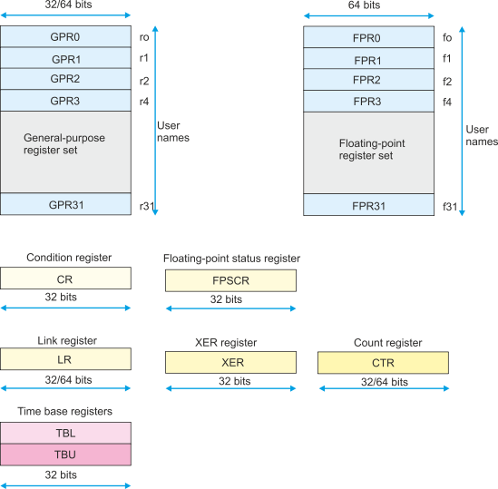
The 32 general-purpose registers are labeled GPR0 to GPR31, although there are writing
r0 to r3 in code are conventional. They are 32 bits wide in 32-bit implementations
of the PowerPC and 64 bits wide in 64-bit implementations. There are also 32 general-purpose
floating-point registers FPR0 to FPR31 (register names in instructions are f0 to
f3). The floating-point registers are 64 bits wide and are accessed by dedicated
floating-point instructions.
Floating-point registers store double-precision 64-bit floating-point values. You
can’t store a single-precision floating-point value in any of the PowerPC’s floating-point
registers. However, you can do single-precision arithmetic; for example, you can
copy two single-precision floating point values to floating-point registers, where
they are converted to double-precision form. You can then, say, add them and store
the result in memory where it it converted back to single-precision form on the way.
We do not delve deeply into the PowerPC’s user visible control and status registers.
These are:
CR (Condition register) The condition register is a 32-bit register divided into
eight 4-bit fields CR0 to CR7. Special instructions are used to manipulate this register
which is used to store the result of comparisons; in some ways, it is a more elaborate
version of the tractictional condition code register.
FPSCR (Floating-point status and control register) This registers both controls the
operation of the floating-point arithmetic unit, and records the status of fp operations.
For example, at the control level, you and enable or disable (mask) floating-point
exceptions, and select the particular rounding mode to be used. At the status level,
the FPSCR provides data about the outcome of an operation; for example, whether a
result is denormalized, or zero, or infinity…
LR (Link register) The link register performs a similar function that in the ARM
or MIPS. It holds a rerun address. The link register is 32 bits in 32-bit versions
of the PowerPC, and 64 bits in 64-bit versions. This link register supplies the target
address for the branch conditional to link register, bclrx, instruction.
XER (Integer Exception Register) The integer exception register is really an extension
of the traditional condition flag register. It contains two overflow bits. SO is
a summary overflow bit that is set whenever an instruction sets the overflow bit,
OV, and it remains set until cleared by software. That is, SO is a sticky overflow
bits that says “overflow has occurred on my watch”. The OV, overflow bit, is a conventional
overflow bit that is set by the generation of an overflow.
CA (Carry) The carry bit is set to indicate that a carry out occurred during the
execution of an instruction.
Byte count The byte count field of the XER register is used to hold the byte count
requires by special loaf string word and store string word instructions.
CTR (Count register) The count register is a 32-bit (or 64-bit in 64-bit versions
of the processor) register that is dedicated to maintaining a loop count. When an
appropriate branch is used, the CTR is decremented and a roll over from 0 to -1 can
be used to terminate the branch.
TBL/TBU (Time base registers) The time base registers provide a real-time, read-only
indication of the time-of-day. I’ve always thought that it was strange that this
register was not a standard features of all processors… In the PowerPC’s user mode,
these registers are read-only. They can be set from the supervisor operating mode;
that is, only the operating system change change them.
Power PC Addressing Modes
I was brought up on the 68K and later the 68020. As you can imagine I thought that
any addressing mode more primitive than ([100,A3,D2.W],64) was embarrassingly crude.
I believed that it was not what you did with data that mattered but how cleverly
you could express its location no matter how deeply it was buried in a data structure.
When I first encountered RISC processors, I was astounded that they provided only
a single simple register indirect addressing format expresses in the form like 4(A3)
or [r2,#6]. So, why had the gods given us complex addressing modes in the first place?
My colleagues explained that the gift of complex addressing modes was a temporary
loan until we’re developed optimizing compilers that could make far better use of
primitive addressing modes.
Both MIPS and ARM have a simple register plus offset addressing mode, although ARM
does allow pre-and post indexing which means you have, at least, a way of automatically
incrementing pointers.
The powerPC has gently extended addressing modes to provide double indexing.
The simplest addressing mode is register with offset; for example, the PowerPC instruction
lwz r3,12(r5) is the same as the ARM equivalent LDR r3,[r5,#12].
The PowerPC’s indexed modes allows the use of two registers and we can write lbzx
r1,(r3,4),r5. The mnemonic indicates load unsigned byte with index. Here, the index
register is r5 and that is used to create the effective address [r3] + 4 + [r5].
WE can also used indexed addressing with update in which the index is permanently
added to pointer register. Updating is indicated by appending a u to the mnemonic
to get lbzxu rather than by adding a ! To the effective address a la ARM.
TO BE EXTENDED